Ask our team:
  • Phone: +86 181 0690 9650
  • E-Mail sales1@apterpower.com
  • Lifecycle status

    Discontinued / Obsolete by OEM
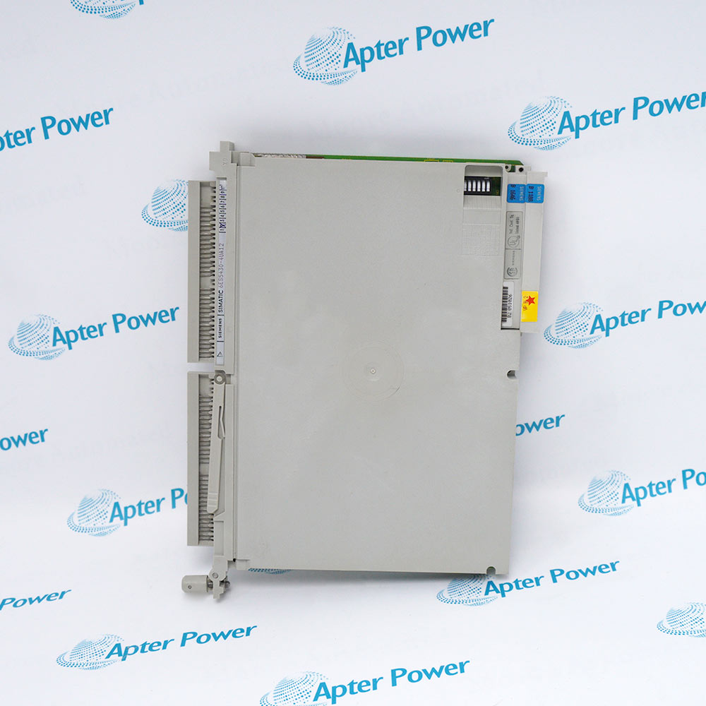
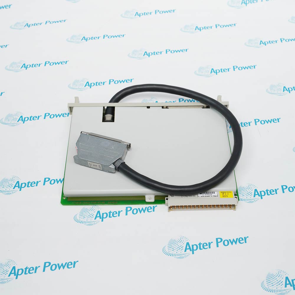
    Apter Power provides 6ES5 541-8AA11 quotations, manuals, bus-parameter checks, and exact-CP matching.

6ES5 541-8AA11

/ 4.9
1001 reviews | Need a Specific Revision?
For SIMATIC S5 network communication, Siemens 6ES5 541-8AA11 is a CP 541 processor that links a controller to SINEC L2 or one DP master.
In Stock
Ships by Wednesday, October 28
Fast Shipping Available
Get a quick price for 6ES5 541-8AA11
Quantity
*E-mail
Company
*Mobile
*Content
Upload (gif, jpg, jpeg, png, bmp, doc, docx, xls, xlsx, ppt, pdf, csv)

Technical specifications for 6ES5 541-8AA11

  • Manufacturer:
    Siemens
  • Part Number:
    6ES5 541-8AA11
  • Product Family:
    Siemens Simatic S5
  • Product Type:
    S5 CP 541 PROFIBUS Communication Processor
  • Stock:
    1
  • Rated Supply Voltage:
    24 V DC
  • Permissible Supply Range:
    20 to 30 V DC
  • Permissible Ripple:
    3 V
  • Typical 24 V Current:
    200 mA
  • Power Dissipation:
    4.8 W
  • Construction:
    IP20, Class I to IEC 536
  • PG/PLC Interface:
    RS485
  • SINEC L2 Interface:
    RS485
  • Communication Modes:
    PLC/PLC, broadcast and DP
  • PLC/PLC Connections:
    Maximum 29
  • Broadcast Connections:
    Maximum 64 bytes
  • DP Connection:
    One DP master connection
  • PLC/PLC Message Length:
    Maximum 125 bytes
  • Broadcast Message Length:
    Maximum 64 bytes
  • DP Message Length:
    Maximum 16 words
  • SINEC L2 Rates:
    9.375, 19.2, 187.5 and 500 kbit/s; 1500 kbit/s
  • Minimum Slave Interval:
    10 ms
  • Manufacturing Identifier:
    001FH
  • Operating Temperature:
    0 to +60 °C horizontally; 0 to +40 °C vertically
  • Relative Humidity:
    15 to 95%, non-condensing
  • Weight:
    0.9149 lbs (0.415 kg)
  • Estimated shipping dimensions:
    16.2x12x4.6cm
  • Tariff Code:
    85176200
  • Country of origin:
    Germany
  • Place of shipment:
    Xiamen,Fujian,China
By purchasing this item, you agree to the Terms & Conditions, ApterPower is not an authorized distributor for listed manufacturers or tradenames and therefore the manufacturer's warranty does not apply. All our products come with ApterPower's 1-year warranty.

More Information

Overview Manuals Interface Roles DB1 Parameters DP Slave Path Power and Faults

Features:

  • The CP 541 links an S5 controller with SINEC L2 over a dedicated RS485 interface.
  • PG/PLC and fieldbus connectors serve different engineering and network paths.
  • DB1 parameters select PLC/PLC, broadcast, or DP-slave communication and assign data areas.
The controller application exchanges data with the processor through its configured blocks.

The CP forms the corresponding L2 telegram and transmits it to the addressed partner.

Power, mode, parameter, and bus indications show where the communication path has stopped.

The Siemens 6ES5 541-8AA11 S5 CP 541 Communication Processor may remain available for quotation and support beyond End-Of-Life (EOL) by the manufacturer (OEM).
Siemens 6ES5 541-8AA11 S5 CP 541 Communication Processor Manuals,Datasheets,Link Important Notice: Other accessories, manuals, cables, calibration data, software, etc. are not included with this equipment unless listed in the above stock item description. All prices are shown in USD.

Separating engineering access from fieldbus traffic

  • PG/PLC port: The upper RS485 connector serves programming or controller communication.
  • L2 port: The lower RS485 connector carries the SINEC L2 network.
  • Mode switch: The selected operating mode determines which service is active.
  • Cable plan: Connector assignment, shield, termination, and bus ends follow the intended topology.

Mapping the software configuration to the communication processor

  • Station address: DB1 assigns the unique SINEC L2 identity.
  • Transmission rate: Every station on the segment uses the configured bus rate.
  • Connection type: PLC/PLC, broadcast, or DP behavior is selected for the required exchange.
  • Data areas: Program words and message buffers are mapped to the intended partners.

Exchanging S5 data with one DP master

  • Master ownership: The connected DP master controls cyclic telegram timing.
  • Input words: Assigned S5 data is returned to the master.
  • Output words: Master commands are written into the configured S5 data area.
  • Status check: DP state and error information confirm parameterization and data exchange.

Tracing a communication stop from supply to telegram

  • Supply input: A 24 V DC source feeds the CP electronics.
  • Front LEDs: Run, stop, bus, and fault indications show the active operating state.
  • Parameter evidence: DB1 and diagnostic data expose an address, rate, or mode mismatch.
  • Network evidence: Cable continuity, termination, partner state, and telegram status locate the bus fault.
Description
Siemens 6ES5 541-8AA11 is the CP 541 communications processor for the SIMATIC S5 controller family. It connects an S5 programmable controller to SINEC L2 through an RS485 fieldbus interface and can also present the controller as a DP slave to one DP master.

Two interfaces divide the communication paths of 6ES5 541-8AA11: the PG/PLC connector links programming or controller equipment, while the SINEC L2 connector carries PLC-to-PLC, broadcast, or DP telegrams. The operating mode determines which partners exchange data and how message areas are assigned.

Parameters stored in DB1 tell 6ES5 541-8AA11 which bus address, transmission rate, connection type, and data areas to use. In DP operation, the master transfers assigned input and output words to the S5 application; in PLC/PLC operation, active and passive stations exchange configured messages across the L2 network.

A separate 24 V DC input powers 6ES5 541-8AA11, while its module electronics connect to the S5 controller through the installed rack arrangement. Front LEDs, connector signals, bus state, and diagnostic information distinguish power, operating-mode, parameter, and network faults during commissioning.
Alternative Names
6ES55418AA11 6ES5 541 8AA11 6ES5541-8AA11 Siemens 6ES5 541-8AA11 6ES5-541-8AA11 CP541 CP 541 6ES5 541-8AA11 6ES5/541/8AA11 6ES5 54I-8AA11
Technical notes
For Siemens 6ES5 541-8AA11, preserve DB1 parameters, PLC/PLC or DP operating mode, SINEC L2 address and rate, PG path, 24 V wiring, and the network termination plan.
Exceptional Service

Our Mission

  • 100% Satisfaction

    We believe expertise is priceless. With over 20 years of experience, and top engineers on staff, we can help you solve or avoid problems that threaten your business.
  • Trust Guaranteed

    Not only do we have a vast inventory, our team makes sure every piece of equipment is in working condition. Your purchases are also backed by our Warranty.
  • Expertise

    Time is money, especially when your equipment is down. We work quickly to get your equipment on its way so you can get it back up and running.

FAQS

The following is a list of questions commonly asked by our customers. Please contact us if you have a question about our process that is not answered below.
Why does Siemens 6ES5 541-8AA11 remain in STOP after power is applied?
Check Siemens 6ES5 541-8AA11 supply voltage, mode-switch position, DB1 parameters, rack connection, SINEC L2 address and rate, partner state, and fault LEDs.
Which interface on 6ES5 541-8AA11 connects to the SINEC L2 network?
The SINEC L2 RS485 connector on 6ES5 541-8AA11 carries PLC/PLC, broadcast, or DP communication; the separate PG/PLC port serves its own access path.
Can Siemens 6ES5 541-8AA11 operate as a DP slave?
Yes. Siemens 6ES5 541-8AA11 can exchange the configured data with one DP master when its mode, DB1 parameters, address, rate, and data areas are correct.
What must be copied before replacing 6ES5 541-8AA11?
Record the 6ES5 541-8AA11 DB1 contents, operating mode, station address, baud rate, active and passive connections, DP word map, cable assignment, and termination.
How is a bus wiring fault separated from a parameter fault on Siemens 6ES5 541-8AA11?
Compare Siemens 6ES5 541-8AA11 LEDs and diagnostics with DB1 settings, then test RS485 polarity, shield, termination, cable continuity, unique addresses, and partner configuration.