Ask our team:
  • Phone: +86 181 0690 9650
  • E-Mail sales1@apterpower.com
  • Lifecycle status

    Discontinued / Obsolete by OEM
    IS200VTURH1B quotation assistance and access to official General Electric turbine-interface documentation for replacement planning are both available through Apter Power.

IS200VTURH1B

/ 4.9
1001 reviews | Need a Specific Revision?
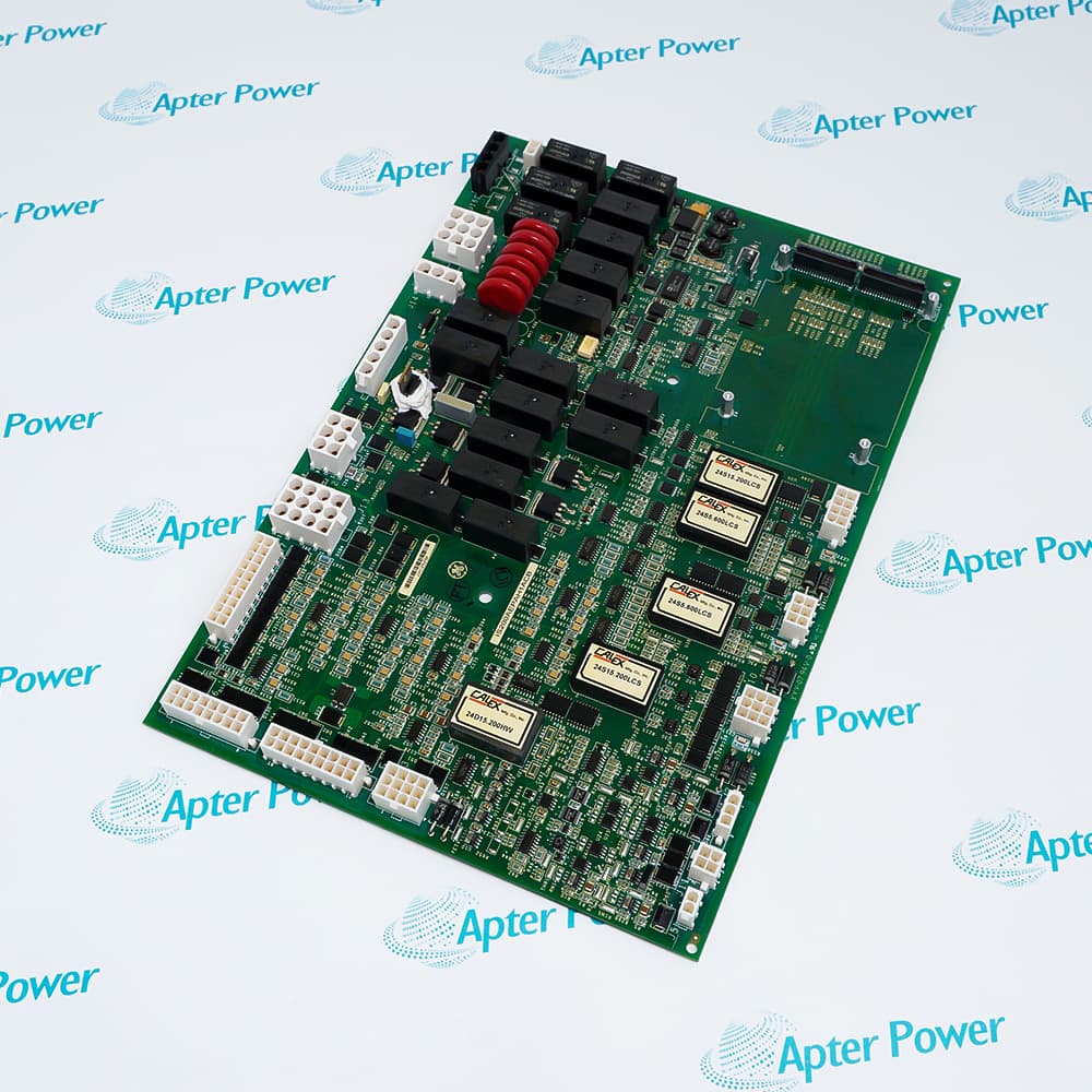
Within SPEEDTRONIC Mark VI, the General Electric IS200VTURH1B VME Turbine Interface Board processes shaft-speed, synchronization, flame, breaker, and trip-path signals.
In Stock
Ships by Wednesday, October 28
Fast Shipping Available
Get a quick price for IS200VTURH1B
Quantity
*E-mail
Company
*Mobile
*Content
Upload (gif, jpg, jpeg, png, bmp, doc, docx, xls, xlsx, ppt, pdf, csv)

Technical specifications for IS200VTURH1B

  • Manufacturer:
    General Electric
  • Part Number:
    IS200VTURH1B
  • Product Family:
    GE Mark VI Gas Turbine Control
  • Product Type:
    VME Turbine Interface Board
  • Stock:
    1
  • Magnetic speed-pickup inputs:
    4 pulse-rate channels
  • Generator and bus PT inputs:
    2 potential-transformer channels
  • Shaft current or voltage inputs:
    2
  • Breaker interface:
    1 coordinated breaker path
  • Flame-detector inputs:
    8 through the trip terminal interface
  • Trip-solenoid drivers:
    3 independent paths
  • Fast overspeed response:
    30 ms or less
  • Synchronization support:
    Generator and bus phase comparison
  • Primary terminal interfaces:
    TTUR and TRPG assemblies
  • Redundancy modes:
    Simplex or triple modular redundant
  • VME form factor:
    Single-width board
  • I/O processor:
    TMS320C32 digital signal processor
  • Controller data exchange:
    VME data path
  • Online diagnostics:
    Speed, trip, terminal, and hardware-identity reporting
  • Hazardous-location listing:
    UL Class I, Division 2, Groups A-D, T4
  • Tariff Code:
    8538900000
  • Country of origin:
    USA
  • Place of shipment:
    Xiamen,Fujian,China
By purchasing this item, you agree to the Terms & Conditions, ApterPower is not an authorized distributor for listed manufacturers or tradenames and therefore the manufacturer's warranty does not apply. All our products come with ApterPower's 1-year warranty.

More Information

Overview Manuals Overspeed Logic Synchronizing Trip Interfaces Field Verification

Features:

  • Measures four magnetic speed-pickup channels for control and fast overspeed protection.
  • Combines generator and bus PT signals with breaker feedback for synchronization.
  • Interfaces eight flame detectors and three trip-solenoid driver paths through Mark VI trip hardware.
The VTUR processor brings turbine speed, generator phasing, breaker state, flame status, and trip commands into one coordinated VME function.

Its fast overspeed path can initiate protective action within 30 ms when the configured limit is exceeded, while the controller continues to receive detailed status and diagnostic data.

Simplex and TMR racks use different signal distributions, so cable destinations and terminal assemblies must match the installed project rather than a generic board diagram.

Apter Power supplies the General Electric IS200VTURH1B VME Turbine Interface Board for qualified Mark VI maintenance and replacement requirements.
General Electric IS200VTURH1B VME Turbine Interface Board Manuals, Datasheets, Links Important Notice: Other accessories, manuals, cables, calibration data, software, etc. are not included with this equipment unless listed in the above stock item description. All prices are shown in USD.

Fast protective speed path

  • Inputs: Four pulse-rate channels accept independent magnetic pickups.
  • Decision basis: Configured speed constants convert pulse frequency to shaft speed.
  • Trip timing: The fast path is designed to act within 30 ms.
  • Redundancy: TMR logic compares the available speed evidence across protection paths.
  • Validity: Missing pulses, noise, or wiring faults must be distinguished from true overspeed.
  • Disagreement check: A channel disagreement should lead first to pickup waveform, polarity, air-gap, and cabling checks, followed by comparison of the configured constants used by IS200VTURH1B.

Generator-to-bus matching

  • Voltage references: Generator and bus PT channels supply the synchronization measurements.
  • Breaker state: The interface tracks breaker feedback used by the permissive sequence.
  • Phase relationship: Phasing and polarity must agree with the plant drawings.
  • Control outcome: Synchronizing logic depends on valid voltage, frequency, and breaker information.
  • Diagnostic sequence: If automatic synchronization stalls, compare PT levels and phase rotation, then trace the breaker indication into IS200VTURH1B before modifying the controller application.
  • Cable preservation: A board exchange should preserve the existing TTUR cable mapping so generator and bus references are not inadvertently reversed.

Protective I/O boundary

  • Flame circuits: Eight detector inputs enter through the trip-terminal hardware.
  • Trip outputs: Three solenoid-driver paths support the shutdown architecture.
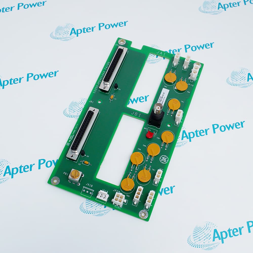
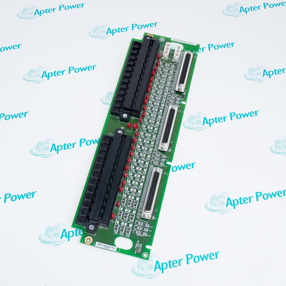
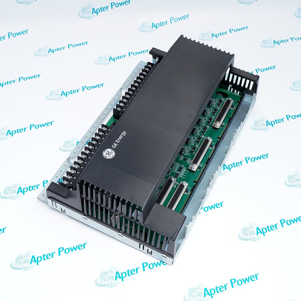
  • Terminal assemblies: TTUR and TRPG hardware connect the field devices to the VME processor.
  • Fail-safe review: Supply, fuse, solenoid, and feedback checks remain part of diagnosis.
  • Hardware identity: Connected board type and revision must match the downloaded configuration.
  • End-to-end proof: IS200VTURH1B status alone cannot prove the health of a flame detector or trip solenoid; terminal power and end-to-end field continuity are required evidence.

Commissioning checkpoints

  • Rack record: Preserve slot number and R/S/T cable destinations before removal.
  • Speed channels: Confirm pickup polarity, air gap, and plausible running speed.
  • PT channels: Verify generator and bus phasing before synchronization is enabled.
  • Trip path: Check flame indications, trip commands, solenoid continuity, and feedback.
  • Final state: Require a healthy RUN indication and cleared hardware-identification alarms.
  • Return-to-service proof: Return IS200VTURH1B to service only after controller values agree with independent field observations and the approved turbine test procedure.
Description
The General Electric IS200VTURH1B VME Turbine Interface Board is the SPEEDTRONIC Mark VI rack module that unites shaft-speed protection and generator synchronizing.

Four pulse-rate inputs accept magnetic speed pickups, while the generator and bus potential-transformer channels provide the phase information needed for synchronization. Additional shaft current or voltage monitoring and breaker-interface paths give IS200VTURH1B a direct role at the boundary between the turbine, generator, and protective hardware.

Eight flame-detector inputs are brought through the trip-terminal assembly, and three independent trip-solenoid driver paths support the protective shutdown architecture. The documented fast overspeed response allows IS200VTURH1B to initiate the trip path within 30 ms when the configured speed limit is exceeded.

Simplex or TMR implementation changes the way speed, trip, and synchronizing signals are distributed, but it does not replace field verification. Correct TTUR/TRPG interfaces, pickup polarity and air gap, potential-transformer phasing, and downloaded hardware identity all need confirmation before IS200VTURH1B is returned to service.
Revisions

Revision Part #

Also known as

IS200VTURH1B
IS200VTURH1-B, Series B, Rev B
Alternative Names
IS200 VTUR H1B IS200-VTUR-H1B IS2OOVTURH1B IS200VTUR H1B IS200VTURHIB GE IS200VTURH1B General Electric IS200VTURH1B Mark VI IS200VTURH1B
Technical notes
IS200VTURH1B participates in the Mark VI fast overspeed path, where shaft-speed evidence and trip-interface health must be evaluated together before a protective fault is attributed to the VME board.
Exceptional Service

Our Mission

  • 100% Satisfaction

    We believe expertise is priceless. With over 20 years of experience, and top engineers on staff, we can help you solve or avoid problems that threaten your business.
  • Trust Guaranteed

    Not only do we have a vast inventory, our team makes sure every piece of equipment is in working condition. Your purchases are also backed by our Warranty.
  • Expertise

    Time is money, especially when your equipment is down. We work quickly to get your equipment on its way so you can get it back up and running.

FAQS

The following is a list of questions commonly asked by our customers. Please contact us if you have a question about our process that is not answered below.
Why does IS200VTURH1B show zero or unstable shaft speed?
Check magnetic-pickup wiring, polarity, air gap, connector seating, and channel diagnostics before replacing IS200VTURH1B; weak or noisy pulse signals can produce the same symptom.
How should an overspeed disagreement involving IS200VTURH1B be investigated?
Compare all available speed channels, verify the configured overspeed constant, and inspect pickup signal quality so IS200VTURH1B is not blamed for a field-sensor mismatch.
What should be checked when IS200VTURH1B cannot complete generator synchronization?
Confirm generator and bus PT phasing, amplitude, breaker feedback, and the synchronizing permissives received by IS200VTURH1B before adjusting the control logic.
Why might a trip solenoid remain energized with IS200VTURH1B installed?
Review the IS200VTURH1B trip commands, TRPG supply and fuses, solenoid continuity, and feedback state because a healthy VME board cannot overcome an open field path.
How can a flame-input fault on IS200VTURH1B be separated from a detector problem?
Trace the affected flame-detector circuit through the terminal assembly, compare neighboring channels, and review IS200VTURH1B diagnostics before exchanging the board.
What should be recorded before replacing IS200VTURH1B in a TMR rack?
Document the IS200VTURH1B rack position, R/S/T cable destinations, TTUR/TRPG hardware revisions, and project configuration so the replacement preserves the approved trip topology.
What should a technician verify after installing IS200VTURH1B?
After powering the rack, confirm IS200VTURH1B RUN status, healthy terminal identification, plausible speed and PT readings, breaker feedback, and a cleared trip path before enabling operation.