Ask our team:
  • Phone: +86 181 0690 9650
  • E-Mail sales1@apterpower.com
  • Lifecycle status

    Discontinued / Obsolete by OEM
    For IS200TREGH1B sourcing support and available General Electric technical material, contact Apter Power.

IS200TREGH1B

/ 4.9
1001 reviews | Need a Specific Revision?
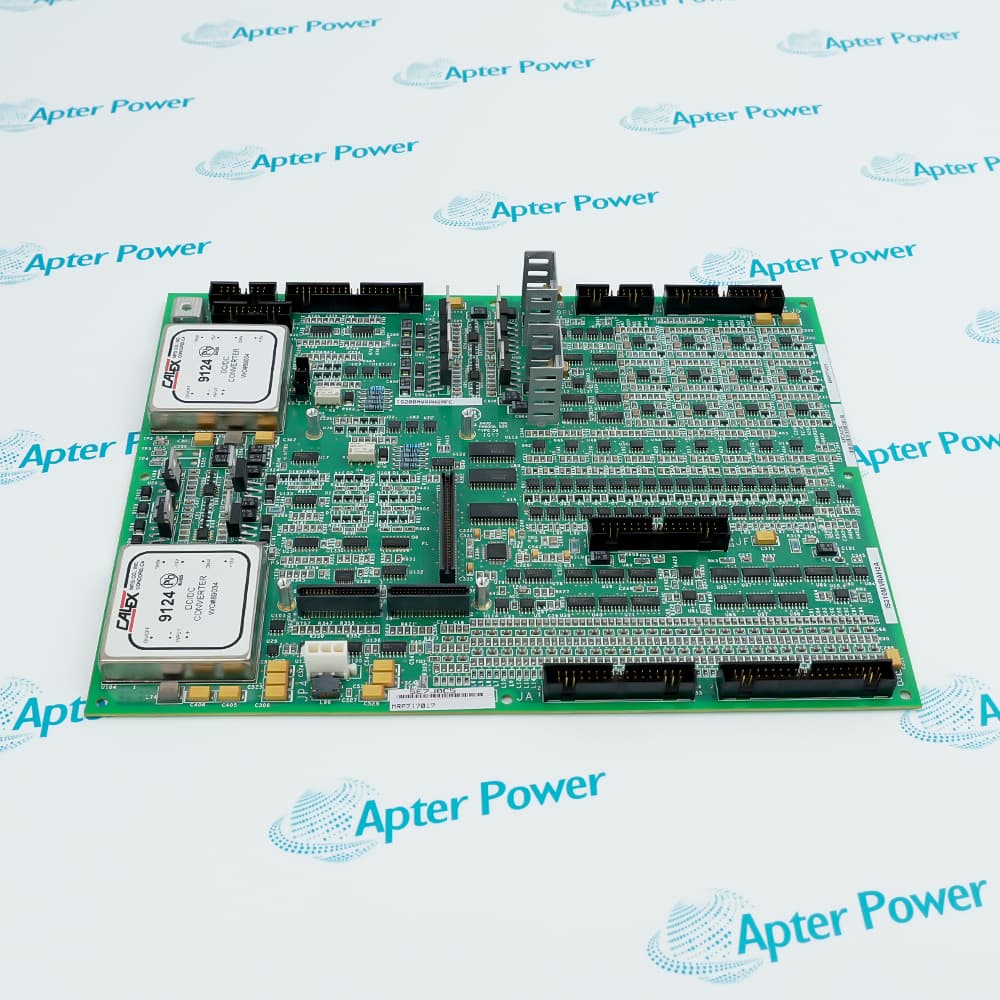
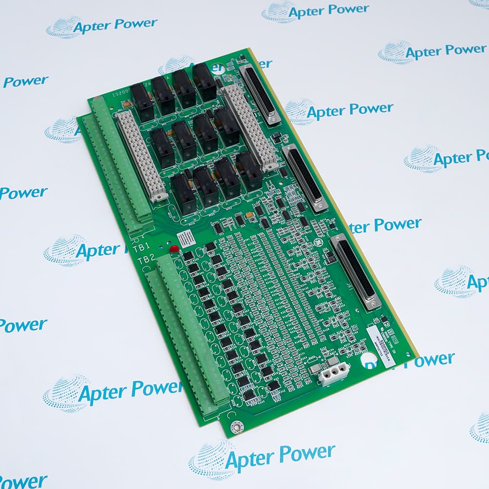
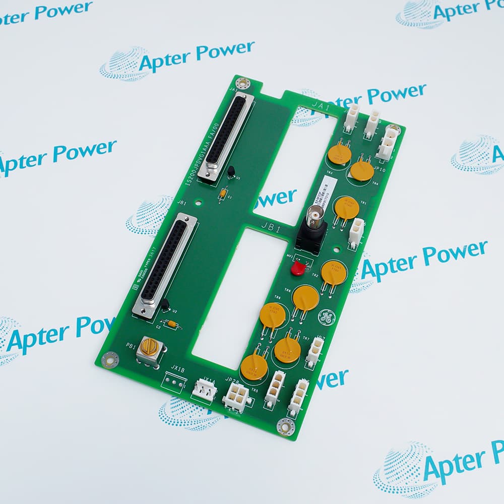
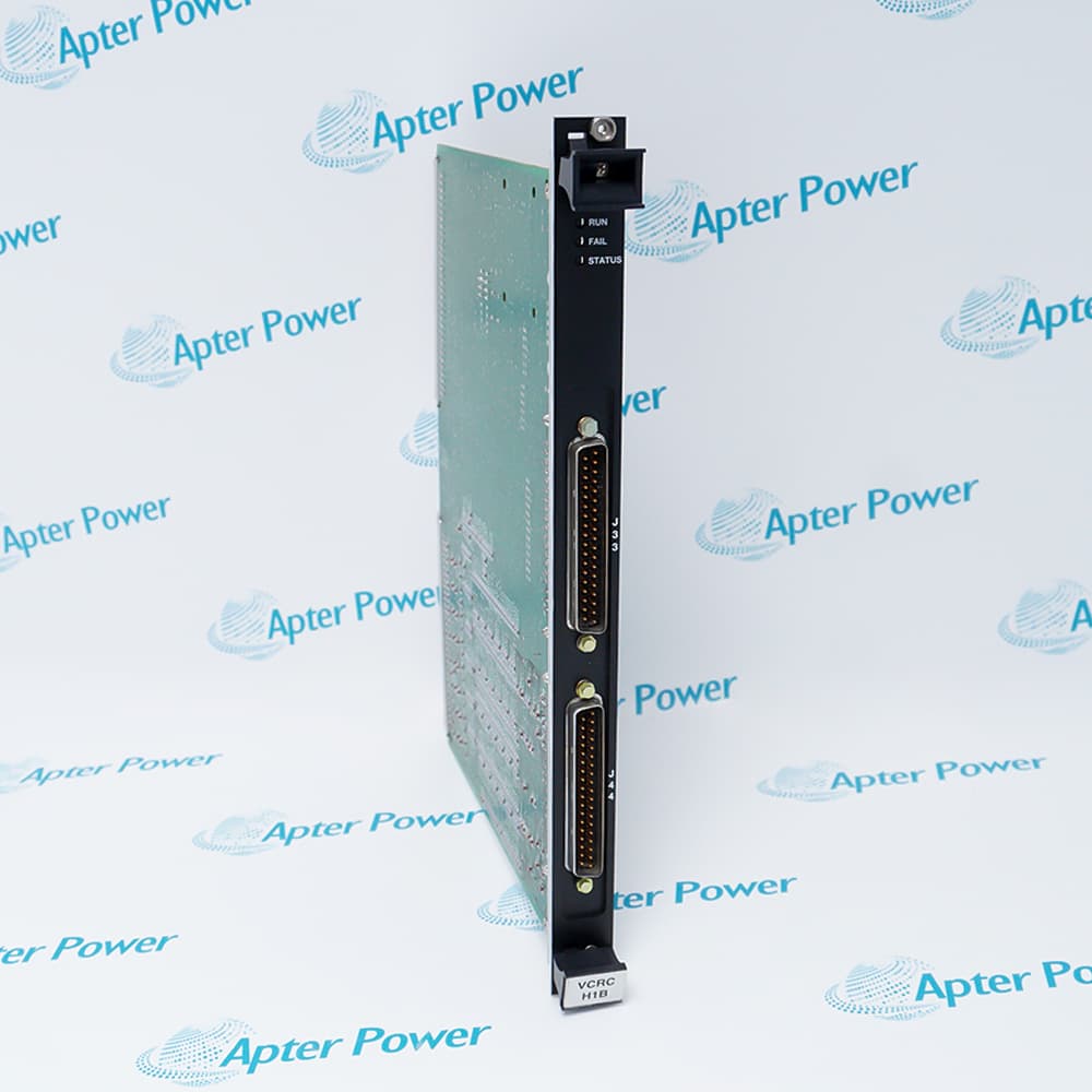
General Electric IS200TREGH1B is a Mark VI emergency trip terminal board that hardware-votes VPRO trip signals and interfaces with turbine trip-solenoid circuits.
In Stock
Ships by Wednesday, October 28
Fast Shipping Available
Get a quick price for IS200TREGH1B
Quantity
*E-mail
Company
*Mobile
*Content
Upload (gif, jpg, jpeg, png, bmp, doc, docx, xls, xlsx, ppt, pdf, csv)

Technical specifications for IS200TREGH1B

  • Manufacturer:
    General Electric
  • Part Number:
    IS200TREGH1B
  • Product Family:
    GE Mark VI Gas Turbine Control
  • Product Type:
    Emergency Trip Terminal Board
  • Stock:
    1
  • Associated Protection Modules:
    Three VPRO modules
  • Protection Layer:
    Independent emergency overspeed
  • Solenoid Drivers:
    6 documented paths
  • Configuration:
    TMR gas-turbine protection
  • Voting Method:
    Hardware relay voting
  • Trip Action:
    Removal of trip-solenoid power
  • Tariff Code:
    8538900000
  • Country of origin:
    USA
  • Place of shipment:
    Xiamen,Fujian,China
By purchasing this item, you agree to the Terms & Conditions, ApterPower is not an authorized distributor for listed manufacturers or tradenames and therefore the manufacturer's warranty does not apply. All our products come with ApterPower's 1-year warranty.

More Information

Overview Manuals Protection Chain Trip-Path Monitoring Shutdown Proof Test Product Applications

Features:

  • Receives independent trip decisions from three Mark VI VPRO protection modules.
  • Combines the three protection channels through hardware relay voting.
  • Controls the positive supply path to three turbine emergency trip solenoids.
IS200TREGH1B belongs to the emergency shutdown layer rather than to the normal Mark VI process-output path.

Separate inputs from the three VPRO channels operate relay groups whose voted state determines whether the trip-solenoid supply remains energized.

The positive-side switching on TREG works with the complementary side of the trip-solenoid circuit, while emergency-stop and interlock terminals remain part of the same independent protection chain.

Quotation and availability support for General Electric IS200TREGH1B Emergency Trip Terminal Board is available through Apter Power.
General Electric IS200TREGH1B Emergency Trip Terminal Board Manuals, Datasheets, Links Important Notice: Other accessories, manuals, cables, calibration data, software, etc. are not included with this equipment unless listed in the above stock item description. All prices are shown in USD.

Building the complete IS200TREGH1B trip-chain record

  • Decision source: Identify the three VPRO channels and retain their correspondence with the voted relay paths.
  • Power route: Mark the supply, protective devices, terminal points, and return path that energize each trip solenoid.
  • Field devices: Record coil resistance, wiring labels, and solenoid assignment before disconnecting a safety circuit.
  • Safe-state controls: Derive bypass and isolation steps from the approved turbine protection procedure, not from a similar cabinet.

Reading IS200TREGH1B command, vote, and field response

  • VPRO indications: Compare all three channel decisions to reveal a single protection path that disagrees with the other two.
  • Relay feedback: Confirm that the hardware-voted contact state follows the expected combination of input decisions.
  • Solenoid voltage: Measure at the field terminals to separate a correct relay operation from a fuse, cable, or coil failure.
  • Economized output: Observe the path after initial pickup as well as at the command edge so a hold-stage problem is not missed.

Proving an IS200TREGH1B shutdown path after service

  • Controlled sequence: Exercise one authorized solenoid path at a time so the remaining protection coverage is known throughout the test.
  • End-to-end result: Verify the VPRO decision, voted relay transition, terminal voltage, solenoid response, and returned status as one traceable event.
  • Failure response: Stop the test if command and feedback disagree; do not mask a field-circuit problem by repeating the logic command.
  • Final restoration: Confirm all test links, bypasses, alarms, and channel states match the approved normal configuration.

Protection duties assigned to IS200TREGH1B

  • Emergency overspeed layer: The board participates in the independent hardware path that removes trip-solenoid power when protection channels demand shutdown.
  • TMR voting interface: Three VPRO sources are combined through relay logic so one channel can be diagnosed without confusing it with the final field circuit.
  • Safety proof testing: The terminal boundary provides measurement points for confirming the response from protection decision to solenoid actuation.
  • Application constraint: This is not a general relay-output board; use remains tied to the documented VPRO, voltage, voting, and trip-solenoid arrangement.
Description
General Electric IS200TREGH1B Emergency Trip Terminal Board is part of the independent Mark VI turbine emergency-trip system controlled by three VPRO protection modules.

Trip decisions from the three VPRO channels reach IS200TREGH1B through separate control connections and are combined by hardware relay voting.

The board switches the positive side of the supply to three emergency trip solenoids, while the complementary trip terminal board controls the opposite side of the solenoid circuit.

IS200TREGH1B also provides the terminal interface for emergency-stop and trip-interlock paths associated with the hardware-voted shutdown chain, keeping this protection layer independent of normal controller software voting.
Alternative Names
IS200-TREG-H1B IS 200 TREG H1B GE IS200TREGH1B GE Mark VI IS200TREGH1B IS200TREG H1B IS2O0TREGH1B IS200TREC H1B IS200TREGH18
Technical notes
IS200TREGH1B belongs to the independent emergency trip chain. Verify VPRO voting, field power, and solenoid circuits before service.
Exceptional Service

Our Mission

  • 100% Satisfaction

    We believe expertise is priceless. With over 20 years of experience, and top engineers on staff, we can help you solve or avoid problems that threaten your business.
  • Trust Guaranteed

    Not only do we have a vast inventory, our team makes sure every piece of equipment is in working condition. Your purchases are also backed by our Warranty.
  • Expertise

    Time is money, especially when your equipment is down. We work quickly to get your equipment on its way so you can get it back up and running.

FAQS

The following is a list of questions commonly asked by our customers. Please contact us if you have a question about our process that is not answered below.
What should be checked when an IS200TREGH1B trip-solenoid path will not energize?
Check the IS200TREGH1B positive-side feed, the corresponding negative-side trip-board path, bus voltage, relay feedback, field wiring, and solenoid coil before replacing the terminal board.
Why are IS200TREGH1B online trip tests performed one solenoid path at a time?
Testing one IS200TREGH1B path at a time preserves the remaining protection paths while contact feedback confirms that the selected relay and solenoid circuit actually responded.
How should IS200TREGH1B be configured when the second emergency-stop input is not used?
IS200TREGH1B requires the documented jumper across terminals 15 and 17 when that second input is absent; otherwise the unused path can remain open and prevent the expected state.
What can trigger a hardware-compatibility alarm after installing IS200TREGH1B?
A mismatched or incorrectly landed JX1, JY1, or JZ1 connection can make the controller read the wrong IS200TREGH1B board identity or plug location.
Why does an IS200TREGH1B economizer output need to be observed beyond initial pickup?
IS200TREGH1B economizer relays change state after the documented delay, so checking only the first instant can miss a failure in the sustained solenoid-control path.
Where should troubleshooting start when several IS200TREGH1B trip interlocks appear open together?
Verify the IS200TREGH1B interlock-excitation source and common field wiring before testing individual contacts, because a shared supply problem can affect multiple optically isolated inputs.
What should a post-replacement proof test demonstrate for IS200TREGH1B?
The IS200TREGH1B test should confirm relay drive and feedback, each trip-solenoid path, emergency-stop continuity, economizer action, and the absence of new connector-identity diagnostics.