Ask our team:
  • Phone: +86 181 0690 9650
  • E-Mail info@apterpower.com
  • Lifecycle status

    Active / Available from OEM
    Apter Power provides documentation, procurement support and system-matching guidance for General Electric IC200ALG431.

IC200ALG431

/ 4.9
1001 reviews | Need a Specific Revision?
General Electric IC200ALG431 combines four 0-10 V analog inputs and two 0-10 V analog outputs in one VersaMax module.
In Stock
Ships by Friday, October 2
Fast Shipping Available
Get a quick price for IC200ALG431
Quantity
*E-mail
Company
*Mobile
*Content
Upload (gif, jpg, jpeg, png, bmp, doc, docx, xls, xlsx, ppt, pdf, csv)

Technical specifications for IC200ALG431

  • Manufacturer:
    General Electric
  • Part Number:
    IC200ALG431
  • Product Family:
    GE VersaMax
  • Product Type:
    4-Input 2-Output Analog Mixed Module
  • Stock:
    1
  • Analog Inputs:
    4 single-ended, 0 to +10 V
  • Analog Outputs:
    2 single-ended, 0 to +10.24 V
  • Resolution:
    12-bit; 2.5 mV per 8 counts
  • Input Update:
    0.4 ms maximum
  • Output Update:
    0.3 ms maximum
  • Field Supply:
    +18 to +30 VDC or 9.6 to 15 VDC
  • Isolation:
    250 VAC continuous; 1500 VAC for 1 minute, user side to logic/frame
  • Diagnostics:
    Loss of user-side power
  • Tariff Code:
    8537101190
  • Country of origin:
    USA
  • Place of shipment:
    Xiamen,Fujian,China
By purchasing this item, you agree to the Terms & Conditions, ApterPower is not an authorized distributor for listed manufacturers or tradenames and therefore the manufacturer's warranty does not apply. All our products come with ApterPower's 1-year warranty.

More Information

Overview Manuals Mixed I/O Input Processing Output Control Field Wiring

Features:

  • Combines four voltage measurements and two voltage commands.
  • Accepts either the documented 24 V-class or 12 V-class field-supply range.
  • Separates input and output conversion timing within one module.
The General Electric IC200ALG431 is the mixed 12-bit choice in this VersaMax group, reducing two analog signal directions to one carrier position without turning them into a single data block.

Input and output words keep their own scaling relationships, so commissioning tests must compare measured field values with the correct side of the module.

When transferring wiring, preserve the alternating input-return pairs, two output pairs, shield terminals, field source and output-default jumper instead of copying a generic analog pinout.

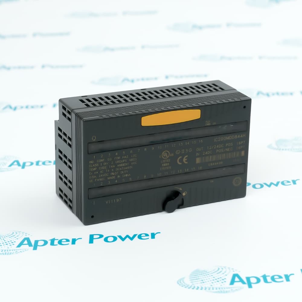
The General Electric IC200ALG431 4-Input 2-Output Analog Mixed Module is supported by Apter Power with documentation and system-matching assistance.
General Electric IC200ALG431 4-Input 2-Output Analog Mixed Module Manuals,Datasheets,LinkImportant Notice: Other accessories, manuals, cables, calibration data, software, etc. are not included with this equipment unless listed in the above stock item description. All prices are shown in USD.

Separate Input and Output Groups

  • Host Input Data: The module returns four analog input words.
  • Host Output Data: Two analog output words are received from the controller.
  • Input Group: All four measurement channels are single-ended and non-isolated from one another.
  • Output Group: Both command channels form a separate single-ended group.

Measurement Path Details

  • Hardware Filter: Each input uses a 5 ms filtering time constant.
  • Scan Time: The four-channel input group updates in no more than 0.4 ms.
  • Input Impedance: The stated minimum impedance is 120 kΩ.
  • Data Step: Returned measurements change in eight-count increments.
  • Rounding: Input conversion rounds upward to the next valid increment.

Command Conversion and Fallback

  • Load Floor: A connected output device must present at least 5 kΩ.
  • Capacitive Limit: The allowed output capacitance is 1.0 µF maximum.
  • Update Time: Both output channels refresh in no more than 0.3 ms.
  • Jumper State: A13-A14 selects hold-last when open and 0 V when linked.

Terminal Assignment Checks

  • Output Pairing: A1-A2 serve output 1, and A3-A4 serve output 2.
  • Input Pairing: A5 through A12 provide four alternating input and return pairs.
  • Shield Bank: B2, B4, B6, B8, B10 and B12 are the listed shield positions.
  • Field Source: A18 is positive field power and A17 is the return.
  • Source Ground: Grounded input sources are preferred where the installation permits.
Description
Mixed voltage signals fit one carrier position with the General Electric IC200ALG431. Four single-ended 0-10 V inputs return four host words, while two single-ended 0-10.24 V outputs accept two controller words in a separate channel group.

Input conversion on the General Electric IC200ALG431 updates in 0.4 ms with a 5 ms hardware filter, whereas the output pair updates in 0.3 ms. Both directions use 12-bit conversion, but their stated count-to-voltage formulas and rounding behavior are different.

Either a +18 to +30 VDC field source or the documented 9.6 to 15 VDC range can operate the General Electric IC200ALG431. Individual input shields, grounded source references and the carrier's earth connection help protect the shared, non-isolated measurement group from wiring noise.
Revisions

Revision Part #

Also known as

IC200ALG431C
IC200ALG431-C, Series C, Rev C
IC200ALG431D
IC200ALG431-D, Series D, Rev D
IC200ALG431F
IC200ALG431-F, Series F, Rev F
IC200ALG431K
IC200ALG431-K, Series K, Rev K
IC200ALG431M
IC200ALG431-M, Series M, Rev M
IC200ALG431N
IC200ALG431-N, Series N, Rev N
Alternative Names
IC200-ALG431 IC200 ALG431 IC 200 ALG 431 GE IC200ALG431 GE Fanuc IC200ALG431 Emerson IC200ALG431 VersaMax IC200ALG431 Mixed Analog Module IC200ALGA31
Technical notes
General Electric IC200ALG431 is a 12-bit VersaMax mixed module with four voltage inputs, two voltage outputs and selectable output fallback.
Exceptional Service

Our Mission

  • 100% Satisfaction

    We believe expertise is priceless. With over 20 years of experience, and top engineers on staff, we can help you solve or avoid problems that threaten your business.
  • Trust Guaranteed

    Not only do we have a vast inventory, our team makes sure every piece of equipment is in working condition. Your purchases are also backed by our Warranty.
  • Expertise

    Time is money, especially when your equipment is down. We work quickly to get your equipment on its way so you can get it back up and running.

FAQS

The following is a list of questions commonly asked by our customers. Please contact us if you have a question about our process that is not answered below.
Noisy inputs but stable outputs on General Electric IC200ALG431 point to which checks?
Separate input and output paths on General Electric IC200ALG431 mean each input shield, source reference and cable route should be checked before the documented 5 ms filter is evaluated.
How should controller counts be compared with field voltage on General Electric IC200ALG431?
General Electric IC200ALG431 uses different equations for input and output data. Apply the 3200-count-per-volt input relationship to measurements and the 10.25 V output relationship to commands, including eight-count resolution.
What can make General Electric IC200ALG431 outputs fall to 0 V after a rack interruption?
General Electric IC200ALG431 uses the A13-A14 jumper for output fallback. When the link is installed, the documented interruption response is 0 V; with it open, the module requests hold-last while field power remains.
Can General Electric IC200ALG431 inputs use unrelated floating references?
General Electric IC200ALG431 places the four inputs in one non-isolated group. Prefer grounded sources where possible and verify every return path against the manual rather than assuming channel-to-channel isolation.
The rack is running while General Electric IC200ALG431 FLD PWR is dark; which source is missing?
General Electric IC200ALG431 separates backplane and user-side power indication. Test the selected field source at A18-A17; the OK light only confirms rack power.
Which connections must remain mapped when General Electric IC200ALG431 moves to another carrier?
Retain the four input-return pairs, two output-return pairs, individual shield points, field-supply terminals and A13-A14 default jumper selection for General Electric IC200ALG431.

Product Browsing History