Ask our team:
  • Phone: +86 181 0690 9650
  • E-Mail info@apterpower.com
  • Lifecycle status

    Discontinued / Obsolete by OEM
    DS200TCCBG8B quotations, official documentation and R5-core matching support are available from Apter Power.

DS200TCCBG8B

/ 4.9
1001 reviews | Need a Specific Revision?
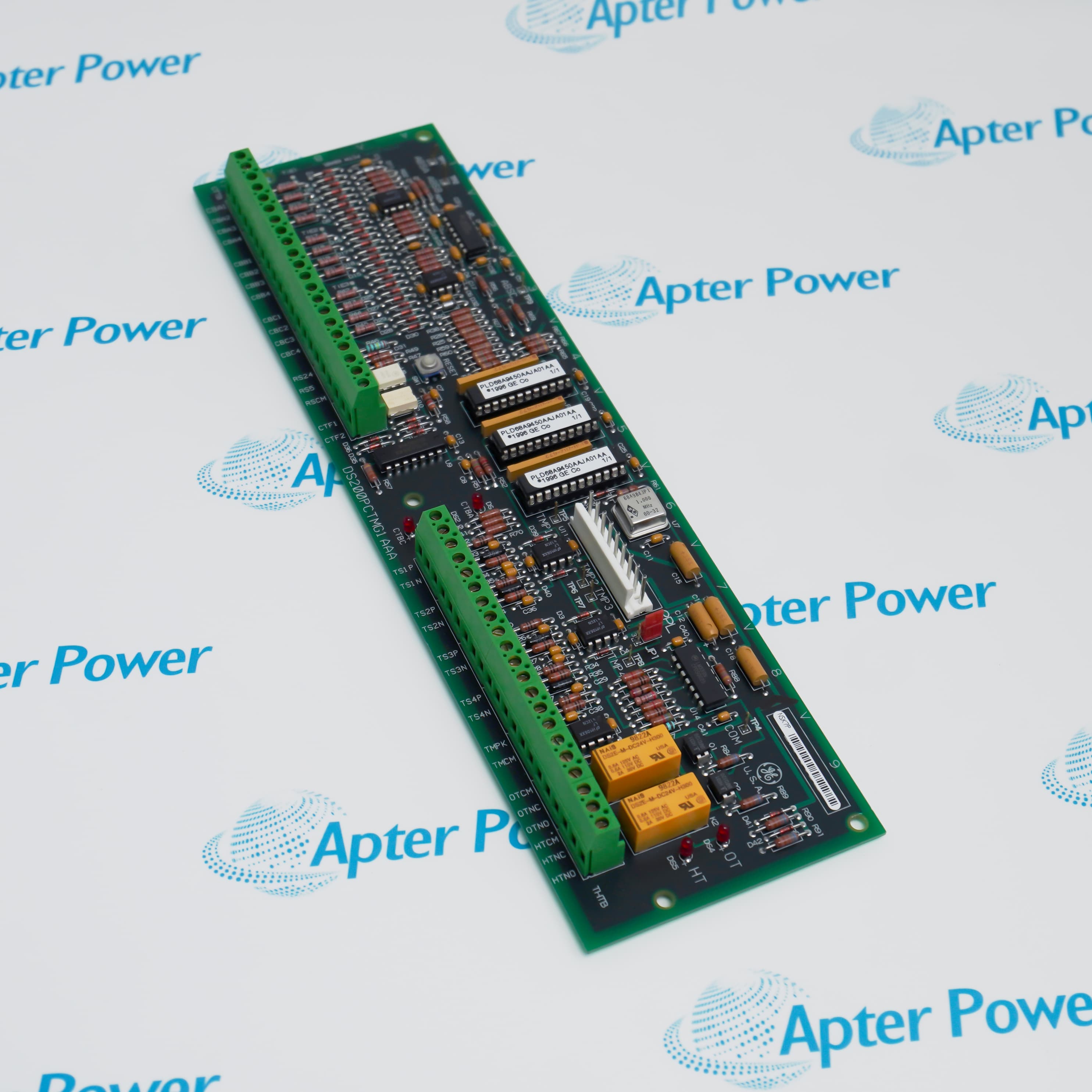
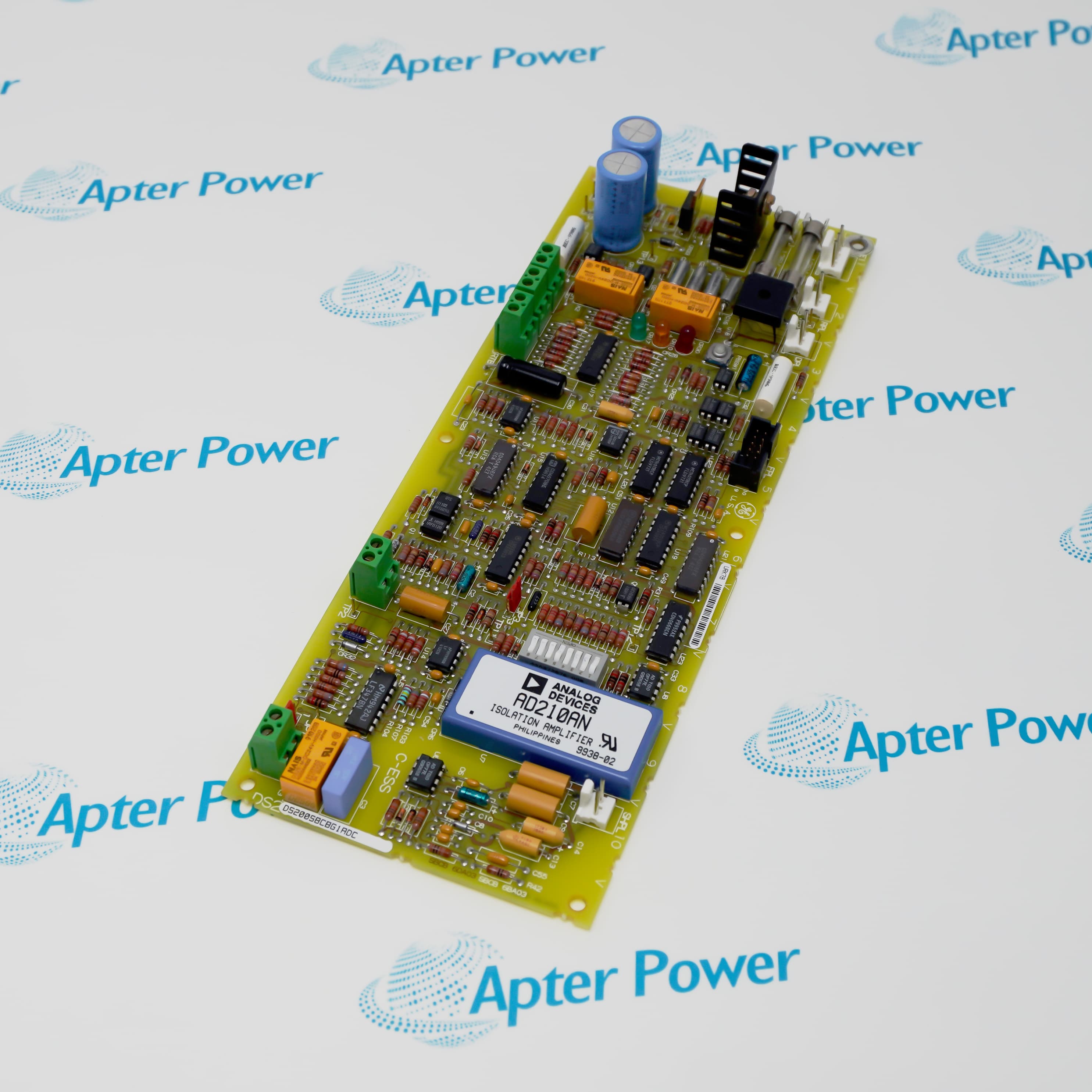
The General Electric DS200TCCBG8B is a Mark V common extended analog I/O board that scales auxiliary sensor and generator electrical signals before STCA processing.
In Stock
Ships by Tuesday, September 29
Fast Shipping Available
Get a quick price for DS200TCCBG8B
Quantity
*E-mail
Company
*Mobile
*Content
Upload (gif, jpg, jpeg, png, bmp, doc, docx, xls, xlsx, ppt, pdf, csv)

Technical specifications for DS200TCCBG8B

  • Manufacturer:
    General Electric
  • Part Number:
    DS200TCCBG8B
  • Product Family:
    SPEEDTRONIC Mark V
  • Product Type:
    Common Extended Analog I/O Board
  • Stock:
    1
  • Board Designation:
    TCCB
  • Core Location:
    R5 core
  • Signal Sources:
    TBCB terminal board and TCEB board
  • Analog Inputs:
    4-20 mA, 0-1 mA and RTD
  • Electrical Inputs:
    Generator/bus voltage and line current
  • Data Destination:
    STCA through 3PL
  • Connections:
    2PL, 3PL, JHH, JII and JMP
  • Tariff Code:
    8537101190
  • Country of origin:
    USA
  • Place of shipment:
    Xiamen,Fujian,China
By purchasing this item, you agree to the Terms & Conditions, ApterPower is not an authorized distributor for listed manufacturers or tradenames and therefore the manufacturer's warranty does not apply. All our products come with ApterPower's 1-year warranty.

More Information

Overview Manuals Signal Conditioning Power Metrics Board Links Monitoring Uses

Features:

  • Conditions extended analog signals arriving from the TBCB and TCEB interfaces.
  • Converts generator voltage and line-current inputs into power-system measurements.
  • Transfers scaled data to STCA through the shared 3PL bus in the R5 core.
DS200TCCBG8B expands the common analog capability beyond the main TCCA paths by accepting extra field and electrical measurements.

Its front-end circuits handle current loops and RTDs, while the PT/CT route supports generator and bus calculations.

Power arrives on 2PL, conditioned data leaves on 3PL and source-specific cabling is separated across JHH, JII and JMP.

Apter Power supports the General Electric DS200TCCBG8B with board identification, sourcing and Mark V configuration assistance.
General Electric DS200TCCBG8B Common Extended Analog I/O Board Manuals, Datasheets, Links Important Notice: Other accessories, manuals, cables, calibration data, software, etc. are not included with this equipment unless listed in the above stock item description. All prices are shown in USD.

Analog Front End

  • Current Loops: JHH brings 4-20 mA and 0-1 mA inputs from TBCB.
  • RTD Excitation: The board supplies excitation and measures RTD resistance changes.
  • Scaling: Input voltages are converted into conditioned control values.
  • Transfer: Processed analog data moves to STCA over 3PL.

Electrical Calculations

  • Potential Inputs: Generator and bus voltage signals originate at PT connections.
  • Current Inputs: Line-current measurements arrive from CT circuits.
  • Derived Values: The board calculates megawatts, power factor and VARs.
  • Monitoring Role: Calculated quantities support Mark V power-system monitoring.

Interface Map

  • 2PL: Supplies board power from TCPS in the R5 core.
  • 3PL: Carries conditioned data among STCA, TCCA and TCCB.
  • JII: Receives RTD signals from the TBCB terminal board.
  • JMP: Brings PT and CT signals from TCEB in the P1 core.

Documented Functions

  • Temperature: Extended RTD channels add monitored temperature points.
  • Process Current: Additional milliamp inputs expand analog measurement capacity.
  • Generator Output: Megawatt and VAR calculations characterize electrical output.
  • Bus Comparison: Generator and bus voltages are available for phase-related monitoring.
Description
In the SPEEDTRONIC Mark V R5 core, General Electric DS200TCCBG8B operates as the TCCB common extended analog I/O board. It scales and conditions additional signals brought in from the TBCB terminal board and from TCEB in the P1 core.

Current-loop and temperature measurements enter General Electric DS200TCCBG8B on dedicated routes. JHH carries 4-20 mA and 0-1 mA inputs, while JII carries RTD channels; the conditioned values then move toward STCA over the 3PL data bus.

Potential- and current-transformer signals reach General Electric DS200TCCBG8B from TCEB through JMP. The board scales generator voltage, bus voltage and line current, then derives phase quantities, megawatts, power factor and VARs for power-system monitoring.

Configuration of General Electric DS200TCCBG8B combines hardware and software choices. Jumpers J1 through J5 support voltage and current monitoring functions, J14 connects the RS-232 port to DCOM, and the related I/O constants define RTD, current, voltage and line-current settings.

Power for General Electric DS200TCCBG8B is distributed from TCPS through 2PL. The 3PL connection links TCCB with STCA and TCCA for COREBUS transfer, while JKK, JTEST and TCQPL are normally unused rather than active field interfaces.
Alternative Names
GE DS200TCCBG8B DS200 TCCB G8B TCCB G8B Extended Analog I/O Board DS200TCCB-G8B Mark V DS200TCCBG8B General Electric DS200TCCB G8B DS 200 TCCB G8B DS2O0TCCBG8B
Technical notes
General Electric DS200TCCBG8B is the R5-core TCCB board for extended analog conditioning and generator power-system measurements.
Exceptional Service

Our Mission

  • 100% Satisfaction

    We believe expertise is priceless. With over 20 years of experience, and top engineers on staff, we can help you solve or avoid problems that threaten your business.
  • Trust Guaranteed

    Not only do we have a vast inventory, our team makes sure every piece of equipment is in working condition. Your purchases are also backed by our Warranty.
  • Expertise

    Time is money, especially when your equipment is down. We work quickly to get your equipment on its way so you can get it back up and running.

FAQS

The following is a list of questions commonly asked by our customers. Please contact us if you have a question about our process that is not answered below.
Why can a current input on General Electric DS200TCCBG8B read incorrectly after rewiring?
General Electric DS200TCCBG8B accepts both 4-20 mA and 0-1 mA paths through JHH; confirm the TBCB range selection and the matching I/O constant.
RTD channels from General Electric DS200TCCBG8B stopped updating; which connections deserve attention?
Inspect the TBCB landing, JII cable and 3PL transfer toward STCA for General Electric DS200TCCBG8B; JMP belongs to a different measurement path.
What should be verified when General Electric DS200TCCBG8B reports implausible generator power values?
Before replacing General Electric DS200TCCBG8B, validate the PT/CT source scaling, JMP connection and related I/O constants against the affected power quantity.
What should be verified if all General Electric DS200TCCBG8B measurements disappear together?
Because 2PL powers General Electric DS200TCCBG8B and 3PL carries its data, a board-wide loss calls for checking both the TCPS feed and the STCA data-bus connection.
Can General Electric DS200TCCBG8B use JKK or JTEST as a normal field-signal connector?
No. JKK and JTEST are typically unused on General Electric DS200TCCBG8B; field sources belong on JHH, JII or JMP according to signal type.
Where are General Electric DS200TCCBG8B voltage and current monitoring jumpers located logically?
J1 through J5 on General Electric DS200TCCBG8B support generator/bus voltage and line-current monitoring, while J14 serves the RS-232-to-DCOM connection.
What prevents General Electric DS200TCCBG8B from being treated as only an RTD card?
Besides RTDs, General Electric DS200TCCBG8B handles two current-input ranges and PT/CT measurements used for electrical power calculations.