3510
3510
3510
3510
3510
3510
Ask our team:
  • Phone: +86 181 0690 9650
  • E-Mail sales1@apterpower.com
  • Lifecycle status

    Active / Available from OEM
    For Triconex 3510, Apter Power offers quotations, product selection, and system matching.

3510

/ 4.9
1001 reviews | Need a Specific Revision?
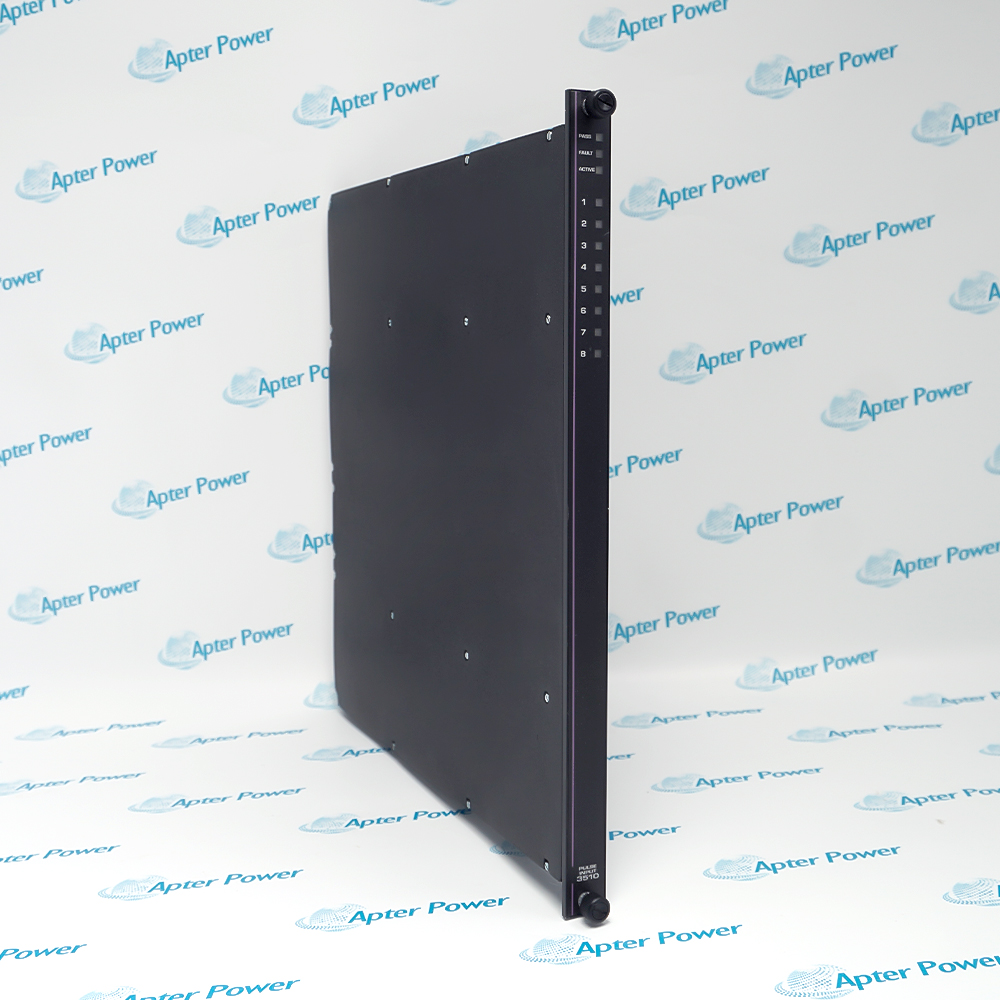
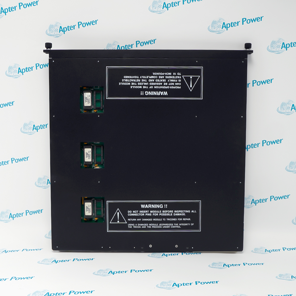
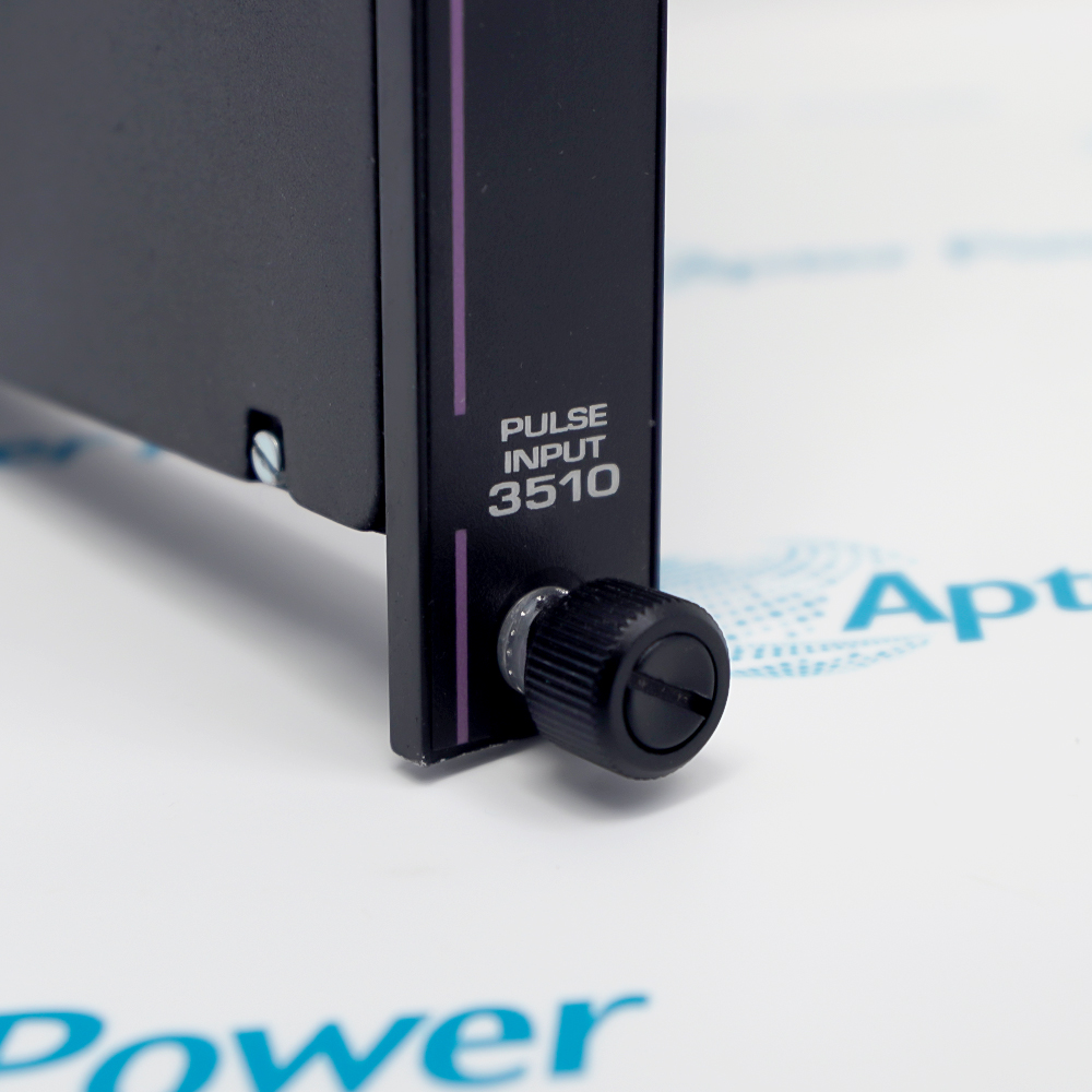
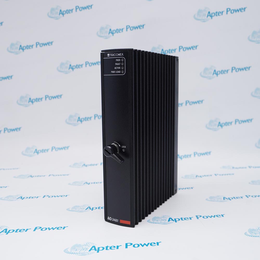
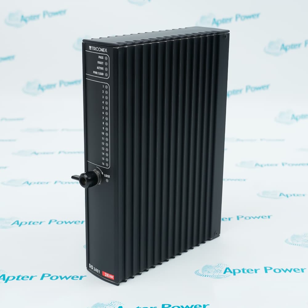
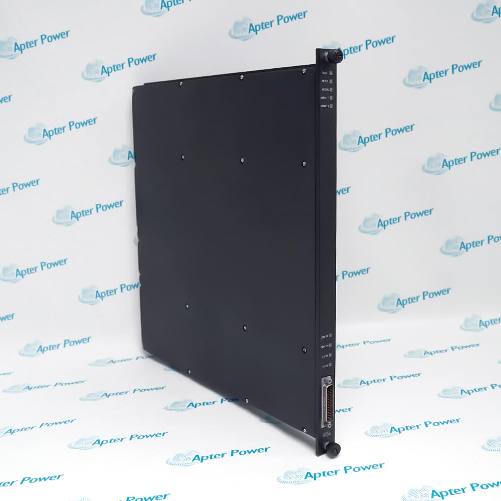
Invensys Triconex 3510 is a TMR pulse input module with eight non-commoned, AC-coupled differential channels for Tricon systems.
In Stock
Ships by Wednesday, October 28
Fast Shipping Available
Get a quick price for 3510
Quantity
*E-mail
Company
*Mobile
*Content
Upload (gif, jpg, jpeg, png, bmp, doc, docx, xls, xlsx, ppt, pdf, csv)

Technical specifications for 3510

  • Manufacturer:
    Invensys
  • Part Number:
    3510
  • Product Family:
    Tricon System
  • Product Type:
    Tricon TMR Pulse Input Module
  • Stock:
    1
  • Input signals:
    8, non-commoned
  • Input coupling:
    AC-coupled, balanced differential
  • Input frequency range:
    20 Hz to 20,000 Hz
  • Accuracy, 1,000–20,000 Hz:
    ±0.01%
  • Accuracy, 100–999 Hz:
    ±0.1%
  • Accuracy, 20–99 Hz:
    ±1.0%
  • Update rate:
    50 ms typical
  • Load impedance:
    Greater than 8 kΩ; 20 kΩ typical
  • Common-mode range:
    -100 V to +100 V peak-to-peak
  • Normal-mode range:
    2.0–200 V p-p below 20 Hz; 1.5–200 V p-p at 20–15,000 Hz; 2.0–200 V p-p above 15,000 Hz
  • Over-range protection:
    ±150 VDC continuous
  • Hysteresis:
    150 mV typical
  • Diagnostic minimum input change:
    0.5% of full scale
  • Diagnostic sample period:
    1 scan or 210 ms, whichever is greater
  • Minimum miscompare period:
    10 samples
  • Point indicators:
    One input-activity indicator per point
  • Module indicators:
    Pass, Fault, Active
  • Logic power:
    Less than 20 W
  • Tariff Code:
    8538900000
  • Country of origin:
    USA
  • Place of shipment:
    Xiamen,Fujian,China
By purchasing this item, you agree to the Terms & Conditions, ApterPower is not an authorized distributor for listed manufacturers or tradenames and therefore the manufacturer's warranty does not apply. All our products come with ApterPower's 1-year warranty.

More Information

Overview Manuals Signal Path Accuracy Diagnostics Field Setup

Features:

  • Eight non-commoned channels keep individual field references separate.
  • Triplicated input paths deliver frequency measurements to the Tricon controller.
  • Point-activity and module-status indicators support distinct visual checks.
Each differential pair enters through AC coupling and feeds the module’s three parallel measurement paths; this topology is meant for pulse-producing sensors, not ordinary dry contacts.

The counting window turns sensor transitions into a rate value, while the applicable accuracy band changes as the measured frequency moves from low to medium or high range.

A 9753-110 field termination panel is documented for this eight-point pulse-input arrangement, so the installed termination assembly and connector keying should be checked before replacement.

The Invensys Triconex 3510 Tricon TMR Pulse Input Module may still be available for purchase and support from Apter Power beyond End-Of-Life (EOL) by the manufacturer (OEM).
Invensys Triconex 3510 Tricon TMR Pulse Input Module Manuals,Datasheets,Link Important Notice: Other accessories, manuals, cables, calibration data, software, etc. are not included with this equipment unless listed in the above stock item description. All prices are shown in USD.

How pulse data reaches the controller

  • Field entry: Each point receives one balanced differential pulse pair through its own non-commoned reference.
  • AC coupling: The front end responds to waveform transitions instead of treating a steady DC level as the measured value.
  • Parallel paths: Three measurement channels count the same source before the controller compares their results.
  • Rate value: Counted transitions become a frequency value for the Tricon application logic.

Selecting the applicable measurement band

  • Low band: Signals from 20 to 99 Hz use the widest documented accuracy allowance.
  • Middle band: The 100 to 999 Hz range uses a tighter tolerance than the low-frequency band.
  • High band: Frequencies from 1,000 to 20,000 Hz use the module’s narrowest published accuracy allowance.
  • Outside range: Detection beyond the nominal limits does not provide a published accuracy or sensitivity guarantee.

Separating signal activity from module status

  • Point indication: One activity indicator per input shows whether transitions are being detected at that channel.
  • Module state: Pass, Fault, and Active indicators report the module-level operating condition separately.
  • Miscompare threshold: A diagnostic difference begins when parallel readings vary by at least 0.5 percent of full scale.
  • Persistence check: Ten samples distinguish a continuing difference from a brief change between measurement paths.

Checks before the input is commissioned

  • Sensor output: Confirm a balanced differential pulse waveform and match its amplitude to the normal-mode limits.
  • Pair assignment: Keep each positive and negative conductor with the same point because channel references are not commoned.
  • Termination: Verify the documented 9753-110 panel and connector keying against the installed Tricon hardware.
  • Acceptance test: Compare the reported frequency with an independent source at the frequencies used by the application.
Description
Invensys Triconex 3510 is an eight-point TMR pulse input module for Tricon systems, converting pulse trains from field speed sensors into frequency or RPM values for the main processors.

Inside Triconex 3510, every differential input is AC-coupled into three independent measurement paths; each path counts transitions over a time window before the main processors vote the reported value.

Because Triconex 3510 evaluates one edge of each pulse, ringing or waveform distortion can create extra counts; signal amplitude, differential wiring, and the 20-20,000 Hz measuring band must therefore be considered together.

One activity indicator per point on Triconex 3510 shows changing pulse inputs, while Pass, Fault, and Active LEDs report the module state and identify a channel diagnostic condition.
Alternative Names
Invensys Triconex 3510 Triconex Model 3510 Tricon 3510 Pulse Input Module 3510 TMR Pulse Input Module 3510 Eight-Channel Frequency Input Invensys 3510 Pulse Input Card Tricon 3510 Speed Input Module Triconex 3510 PI Module
Technical notes
Invensys Triconex 3510 compares triplicated frequency measurements; rapidly changing inputs can produce miscompares when channels differ by at least 0.5% of full scale.
Exceptional Service

Our Mission

  • 100% Satisfaction

    We believe expertise is priceless. With over 20 years of experience, and top engineers on staff, we can help you solve or avoid problems that threaten your business.
  • Trust Guaranteed

    Not only do we have a vast inventory, our team makes sure every piece of equipment is in working condition. Your purchases are also backed by our Warranty.
  • Expertise

    Time is money, especially when your equipment is down. We work quickly to get your equipment on its way so you can get it back up and running.

FAQS

The following is a list of questions commonly asked by our customers. Please contact us if you have a question about our process that is not answered below.
Which sensor outputs should be screened before connecting Triconex 3510?
Before wiring Triconex 3510, confirm that the source is a balanced differential pulse signal and compare its amplitude and frequency with the applicable input ranges. A dry contact or an unconditioned signal outside those limits should not be assigned as though it were a normal pulse source.
When does Triconex 3510 require a different accuracy allowance across its operating range?
Triconex 3510 has separate accuracy bands for 20–99 Hz, 100–999 Hz, and 1,000–20,000 Hz. Use the tolerance from the band containing the expected speed or rate, then test acceptance limits at the actual operating frequency.
Why can rapidly changing inputs cause a miscompare on Triconex 3510?
The three measurement paths in Triconex 3510 can briefly report values that differ by 0.5% of full scale or more when frequency changes quickly. Review the trend and the ten-sample persistence condition before treating the event as a stable hardware fault.
How should the eight field pairs be transferred during a Triconex 3510 replacement?
Keep every positive/negative pair and its shield assignment tied to the same Triconex 3510 point; the inputs are non-commoned. Verify the installed 9753-110 termination panel and connector keying, then compare the measured frequency with an independent reference before returning the loop to service.
What does operation outside 20–20,000 Hz mean for Triconex 3510?
Triconex 3510 may detect signals below 20 Hz or above 20,000 Hz, but the documented accuracy and sensitivity are not defined there. Do not qualify that condition from the nominal table; obtain an approved limit from the system authority or manufacturer support.
Is the ±150 VDC figure a normal signal level for Triconex 3510?
No. For Triconex 3510, ±150 VDC is a continuous over-range protection rating, not the permitted normal pulse amplitude. Compare the sensor waveform with the normal-mode peak-to-peak limits before energizing the input.