Ask our team:
  • Phone: +86 181 0690 9650
  • E-Mail sales1@apterpower.com
  • Lifecycle status

    Discontinued / Obsolete by OEM
    Apter Power coordinates manuals, selection, quotations, and exact-model matching for 6ES7351-1AH02-0AE0.

6ES7351-1AH02-0AE0

/ 4.9
1001 reviews | Need a Specific Revision?
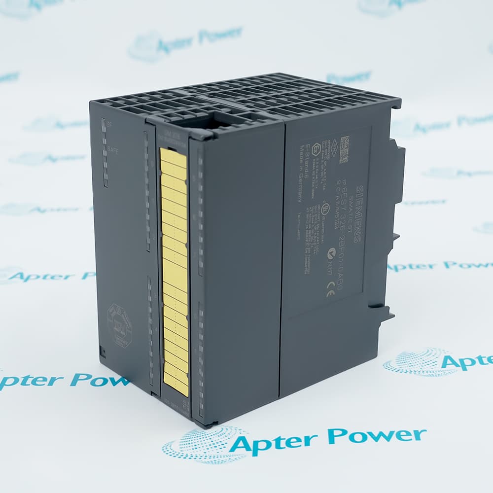
The Siemens 6ES7351-1AH02-0AE0 FM 351 positioning module processes axis feedback and controls rapid/creep drives in a SIMATIC S7-300 system.
In Stock
Ships by Wednesday, October 28
Fast Shipping Available
Get a quick price for 6ES7351-1AH02-0AE0
Quantity
*E-mail
Company
*Mobile
*Content
Upload (gif, jpg, jpeg, png, bmp, doc, docx, xls, xlsx, ppt, pdf, csv)

Technical specifications for 6ES7351-1AH02-0AE0

  • Manufacturer:
    Siemens
  • Part Number:
    6ES7351-1AH02-0AE0
  • Product Family:
    Siemens Simatic S7-300
  • Product Type:
    SIMATIC S7-300 FM 351 Positioning Module
  • Stock:
    1
  • Positioning Method:
    Rapid/creep traverse
  • Rated Supply:
    24 V DC
  • Supply Range:
    20.4 to 28.8 V DC
  • Maximum Supply Current:
    350 mA
  • Backplane Current:
    Maximum 150 mA at 5 V DC
  • Power Loss:
    7.9 W
  • Digital Inputs:
    8
  • Digital Outputs:
    8
  • Input Functions:
    Reference cams, reversing cams, flying actual value, start/stop
  • Output Functions:
    Rapid, creep, right and left commands
  • Output Protection:
    Short-circuit protected
  • 5 V Encoder Supply:
    Maximum 350 mA
  • 5 V Encoder Cable Length:
    Maximum 32 m
  • 24 V Encoder Supply:
    Maximum 400 mA per channel
  • 24 V Encoder Cable Length:
    Maximum 100 m
  • Weight:
    1.0935 lbs (0.496 kg)
  • Estimated shipping dimensions:
    13.2x15.3x9.1cm
  • Tariff Code:
    85389091
  • Country of origin:
    Germany
  • Place of shipment:
    Xiamen,Fujian,China
By purchasing this item, you agree to the Terms & Conditions, ApterPower is not an authorized distributor for listed manufacturers or tradenames and therefore the manufacturer's warranty does not apply. All our products come with ApterPower's 1-year warranty.

More Information

Overview Manuals Axis Control Encoder Paths Digital I/O Configuration

Features:

  • Encoder feedback supplies the actual position used by the FM 351 control sequence.
  • Rapid, creep, right and left outputs translate the position decision into drive commands.
  • Eight digital inputs bring reference, reversing, capture and start/stop conditions into the module.
The module treats position feedback, machine-state inputs and drive commands as related but separate signal paths.

As the axis approaches its destination, the configured change from rapid to creep output controls the final approach.

Encoder voltage, current and cable length determine how the feedback device can be connected.

The Siemens 6ES7351-1AH02-0AE0 SIMATIC S7-300 FM 351 Module may still be available for purchase and support from Apter Power beyond End-Of-Life (EOL) by the manufacturer (OEM).
Siemens 6ES7351-1AH02-0AE0 S7-300 FM 351 Manuals,Datasheets,Link Important Notice: Other accessories, manuals, cables, calibration data, software, etc. are not included with this equipment unless listed in the above stock item description. All prices are shown in USD.

Turning position comparison into drive commands

  • Destination: The configured target provides the endpoint for the positioning sequence.
  • Actual value: Encoder feedback supplies the changing axis position.
  • Speed change: The output sequence moves from rapid traverse to creep speed near the destination.
  • Direction: Separate right and left commands tell the connected drive which way to move.

Matching encoder supply and signal distance

  • 5 V supply: The 5 V encoder path is rated up to 350 mA with a maximum 32 m cable.
  • 24 V supply: The 24 V encoder path is rated up to 400 mA per channel with a maximum 100 m cable.
  • Feedback role: Encoder pulses describe movement independently of the digital machine-state inputs.
  • Selection check: Encoder voltage, current demand and cable run must fit the same documented path.

Separating machine conditions from drive outputs

  • Input group: Eight inputs accept reference cams, reversing cams, flying actual value and start/stop signals.
  • Output group: Eight outputs provide the rapid, creep and direction command structure.
  • Protection: The digital outputs include short-circuit protection.
  • Signal boundary: Machine-state inputs do not replace the separate encoder feedback connection.

Aligning module parameters with the axis

  • Drive behavior: Rapid and creep transition points must match the mechanical movement.
  • Reference logic: Reference and reversing cam assignments must agree with the field wiring.
  • Feedback scale: Encoder evaluation must represent the actual travel per pulse.
  • Project match: The S7-300 hardware configuration must use the complete FM 351 order number.
Description
Positioning for rapid/creep drives is handled by Siemens 6ES7351-1AH02-0AE0, a SIMATIC S7-300 FM 351 module that evaluates encoder feedback and issues speed and direction commands.

During a movement, 6ES7351-1AH02-0AE0 compares the changing actual position with the configured destination. Its output sequence changes from rapid traverse to creep speed before the target, while the right and left signals define the commanded direction.

Reference cams, reversing cams and start/stop signals enter 6ES7351-1AH02-0AE0 through the digital input group. These inputs describe the machine state and travel limits separately from the encoder channel that supplies position feedback.

Encoder power and signal distance must be planned together for 6ES7351-1AH02-0AE0. The documented 5 V and 24 V encoder supplies have different current and cable-length limits, while the short-circuit-protected outputs remain part of the drive-command path.
Alternative Names
6ES73511AH020AE0 6ES7351 1AH02 0AE0 6ES7 351-1AH02-0AE0 Siemens 6ES73511AH020AE0 FM 351 6ES7351-1AH02-0AE0 S7-300 6ES7351-1AH02-0AE0 6ES7351-1AHO2-0AE0 6ES7351-IAH02-0AE0
Technical notes
Encoder feedback enters Siemens 6ES7351-1AH02-0AE0 separately from its rapid, creep and direction outputs, so both paths require matching configuration.
Exceptional Service

Our Mission

  • 100% Satisfaction

    We believe expertise is priceless. With over 20 years of experience, and top engineers on staff, we can help you solve or avoid problems that threaten your business.
  • Trust Guaranteed

    Not only do we have a vast inventory, our team makes sure every piece of equipment is in working condition. Your purchases are also backed by our Warranty.
  • Expertise

    Time is money, especially when your equipment is down. We work quickly to get your equipment on its way so you can get it back up and running.

FAQS

The following is a list of questions commonly asked by our customers. Please contact us if you have a question about our process that is not answered below.
Why can 6ES7351-1AH02-0AE0 move an axis in the wrong direction?
Compare the right and left output assignments of 6ES7351-1AH02-0AE0 with the drive wiring and mechanical direction. Also verify encoder counting direction so commanded motion and reported position change agree.
What causes 6ES7351-1AH02-0AE0 to miss the target after rapid traverse?
Review the rapid-to-creep transition and encoder scaling configured for 6ES7351-1AH02-0AE0. A late speed change or incorrect travel-per-pulse value can leave too little distance for the final approach.
Which limits matter when selecting an encoder for 6ES7351-1AH02-0AE0?
Match the encoder voltage and current demand to the corresponding supply on 6ES7351-1AH02-0AE0. Then keep the cable within the documented 32 m limit for 5 V or 100 m limit for 24 V.
How are cam signals used by 6ES7351-1AH02-0AE0?
Reference and reversing cams enter the digital input group of 6ES7351-1AH02-0AE0 to describe axis position boundaries and homing conditions. They complement the encoder feedback rather than replacing it.
A drive does not respond to 6ES7351-1AH02-0AE0; which output checks come first?
Check the rapid, creep, right and left outputs of 6ES7351-1AH02-0AE0 against the active positioning state. If an output is missing, inspect short-circuit status and the corresponding drive-command wiring.
Why must start/stop wiring be distinguished from encoder wiring on 6ES7351-1AH02-0AE0?
Start and stop are discrete control conditions for 6ES7351-1AH02-0AE0, while the encoder reports continuous movement. Mixing those roles prevents the module from relating an operating command to a valid position value.