EB401-50 S1
EB401-50 S1
EB401-50 S1
EB401-50 S1
EB401-50 S1
EB401-50 S1
Ask our team:
  • Phone: +86 181 0690 9650
  • E-Mail sales1@apterpower.com
  • Lifecycle status

    Active / Available from OEM
    Apter Power provides quotations, technical documents, sourcing, and ER Bus topology guidance for this master module.

EB401-50 S1

/ 4.9
1001 reviews | Need a Specific Revision?
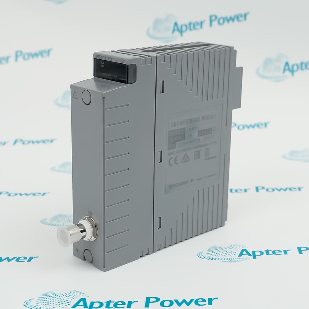
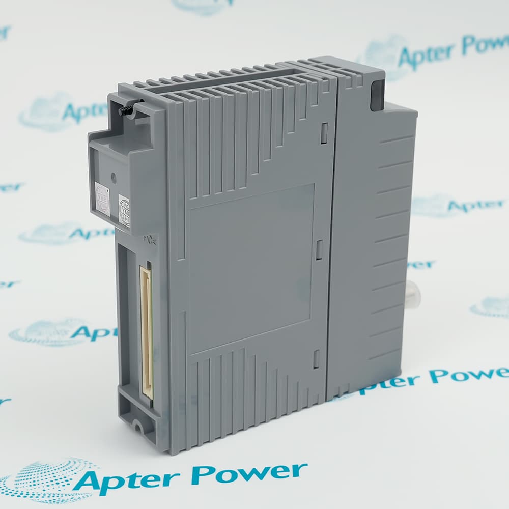
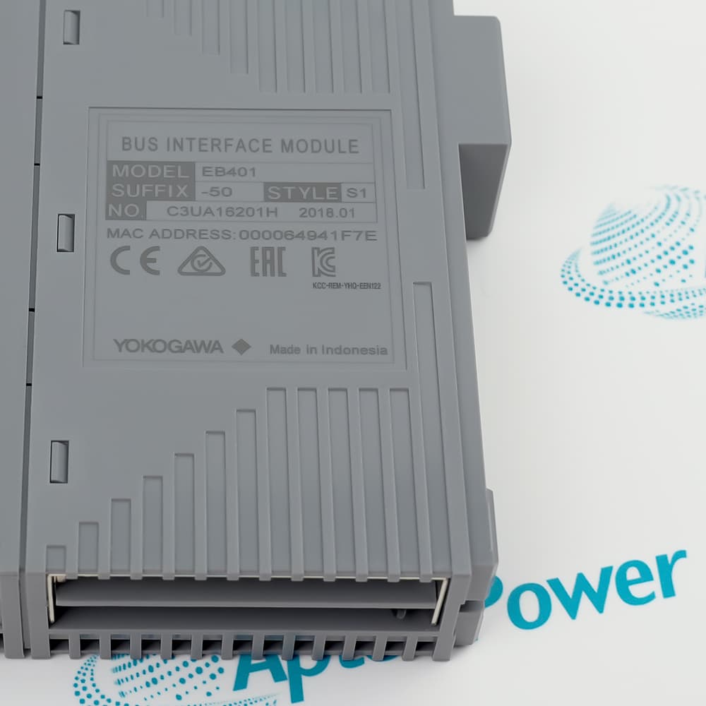
Yokogawa EB401-50 S1 is an ER Bus Interface Master Module that links a local ESB Bus node or compact FCU to remote ER Bus nodes.
In Stock
Ships by Thursday, October 29
Fast Shipping Available
Get a quick price for EB401-50 S1
Quantity
*E-mail
Company
*Mobile
*Content
Upload (gif, jpg, jpeg, png, bmp, doc, docx, xls, xlsx, ppt, pdf, csv)

Technical specifications for EB401-50 S1

  • Manufacturer:
    Yokogawa
  • Part Number:
    EB401-50 S1
  • Product Family:
    Centum CS-Centum VP
  • Product Type:
    ER Bus Interface Master Module
  • Stock:
    1
  • Module Role:
    ER Bus interface master
  • Network Interface:
    IEEE 802.3 10BASE2, BNC
  • Transmission Speed:
    10 Mbps
  • Maximum Cable Length:
    185 m with YCB141
  • Current Consumption:
    0.7 A
  • Redundancy:
    Single or dual-redundant configuration
  • Order Suffix:
    -50: standard type, no explosion protection
  • Weight:
    0.25 kg
  • Estimated shipping dimensions:
    3.2 x 14.5 x 13 cm
  • Tariff Code:
    Please confirm the destination before shipping
  • Country of origin:
    Japan
  • Place of shipment:
    Xiamen,Fujian,China
By purchasing this item, you agree to the Terms & Conditions, ApterPower is not an authorized distributor for listed manufacturers or tradenames and therefore the manufacturer's warranty does not apply. All our products come with ApterPower's 1-year warranty.

More Information

Overview Manuals Specifications ER Topology Redundancy Bus Acceptance

Features:

  • ER Bus master connection between local and remote nodes
  • 10BASE2 BNC communication at 10 Mbps
  • Single or dual-redundant module arrangement
Yokogawa EB401-50 S1 provides the master-side interface for extending an approved ER Bus from a local ESB Bus node or compact FCU.

The coaxial segment uses the specified BNC media and termination method, so cable type, route length, connectors, and terminators form part of the engineered network.

Module placement differs between single and redundant arrangements; record the installed slot plan and peer condition before replacing hardware.

Availability of Yokogawa EB401-50 S1 is subject to Apter Power inventory and sourcing confirmation.
zhVerified resources for Yokogawa EB401-50 S1: Important Notice: Other accessories, manuals, cables, calibration data, software, etc. are not included with this equipment unless listed in the above stock item description. All prices are shown in USD.
Yokogawa EB401-50 S1 ER Bus Interface Master Module Specs

General

  • ManufacturerYokogawa
  • ModelEB401-50 S1
  • ConditionNew Original ready stock
  • Product FamilyCENTUM ER Bus Interface Modules
Important Notice: Other accessories, manuals, cables, calibration data, software, etc. are not included with this equipment unless listed in the above stock item description. All prices are shown in USD.

Network design points

  • Master location: Identify the local ESB Bus node or compact FCU hosting the module.
  • Approved media: Use the documented YCB141 50-ohm coaxial cable and BNC components.
  • Distance limit: Keep the segment within the specified maximum cable length.
  • Node record: Preserve remote-node addresses, route drawings, and termination locations.

Module arrangement

  • Single service: Use the designated odd-numbered slot and maintain the required empty adjacent position.
  • Redundant pair: Treat both masters as one engineered pair with recorded active and standby status.
  • Changeover plan: Follow the site procedure before disturbing a healthy peer module.
  • Alarm review: Confirm that redundancy and communication alarms clear after replacement.

Post-installation checks

  • Connector inspection: Check BNC seating, cable strain, tees, and terminators.
  • Node communication: Confirm stable access to every configured remote ER Bus node.
  • Recovery test: Observe bus recovery after a controlled interruption.
  • Documentation: Update slot records, cable route, node map, and commissioning results.
Description
The EB401-50 S1 is Yokogawa’s ER Bus Interface Master Module for connecting a local ESB Bus node or compact field control unit to remote ER Bus nodes. The documented interface uses 10BASE2 communication through a BNC connection.

A control architecture can use EB401-50 S1 in a single or dual-redundant arrangement. With Yokogawa YCB141 cable, one ER Bus segment can extend to the documented maximum distance while preserving the approved node topology and termination method.

Before replacing EB401-50 S1, identify the occupied slot, redundancy arrangement, peer module, cable type, BNC termination, and node configuration. A single installation requires the specified slot arrangement, while a redundant pair must be maintained as an engineered pair rather than treated as two independent masters.
Alternative Names
EB401 50 S1 EB40150S1 EB401-50S1 EB401 50-S1 Yokogawa EB401 50 S1
Technical notes
Install EB401-50 S1 according to the documented ER Bus topology: a single master uses the designated odd-numbered slot with the adjacent slot left empty, while redundant service requires the approved pair arrangement. Preserve YCB141 cable length, 50-ohm BNC termination, node settings, and peer-module status during replacement.
Exceptional Service

Our Mission

  • 100% Satisfaction

    We believe expertise is priceless. With over 20 years of experience, and top engineers on staff, we can help you solve or avoid problems that threaten your business.
  • Trust Guaranteed

    Not only do we have a vast inventory, our team makes sure every piece of equipment is in working condition. Your purchases are also backed by our Warranty.
  • Expertise

    Time is money, especially when your equipment is down. We work quickly to get your equipment on its way so you can get it back up and running.

FAQS

The following is a list of questions commonly asked by our customers. Please contact us if you have a question about our process that is not answered below.
How does the documented slot rule affect a single EB401-50 S1 installation?
Use the designated odd-numbered slot and leave the adjacent slot empty; treating the spare position as available can invalidate the approved ER Bus arrangement.
What must be preserved when EB401-50 S1 operates as a redundant master pair?
Record both slot positions, peer-module identity, node settings, cable route, and status behavior so the pair is restored as one engineered redundancy arrangement.
Where should 50-ohm termination be checked around EB401-50 S1?
Inspect both BNC interfaces, the YCB141 route, and the terminator at the documented end of the ER Bus segment; an open or misplaced terminator can disrupt the bus.
How should engineers apply the 185 m cable limit for EB401-50 S1?
Measure the complete approved YCB141 segment between the master and remote node, including routing, and keep the topology and termination within Yokogawa's documented maximum.
Which commissioning results should be recorded after replacing EB401-50 S1?
Record module status, communication with every configured ER Bus node, redundancy transfer where used, termination condition, bus recovery, and stable operation after restoration.
What site data makes an EB401-50 S1 purchase request actionable?
Include the full suffix and style, slot and redundancy plan, peer module, node count, YCB141 route length, BNC termination layout, quantity, and destination.