Ask our team:
  • Phone: +86 181 0690 9650
  • E-Mail sales1@apterpower.com
  • Lifecycle status

    Discontinued / Obsolete by OEM
    For IS200TRLYH1B quotations, revision review, and relevant General Electric documentation, contact Apter Power.

IS200TRLYH1B

/ 4.9
1001 reviews | Need a Specific Revision?
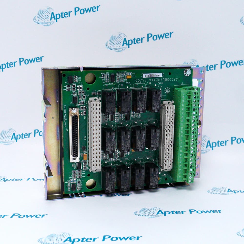
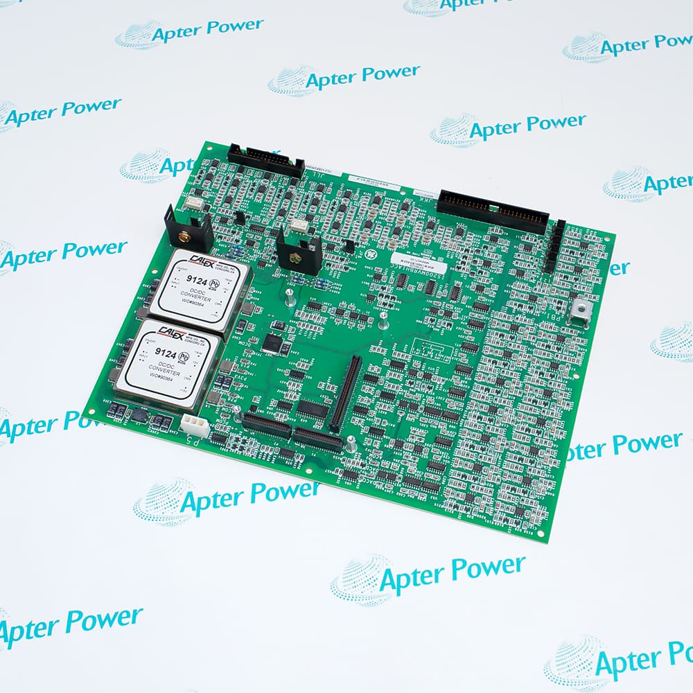
General Electric IS200TRLYH1B is a Mark VI relay output terminal board that connects VCCC or VCRC I/O channels with customer-powered relay and solenoid circuits.
In Stock
Ships by Wednesday, October 28
Fast Shipping Available
Get a quick price for IS200TRLYH1B
Quantity
*E-mail
Company
*Mobile
*Content
Upload (gif, jpg, jpeg, png, bmp, doc, docx, xls, xlsx, ppt, pdf, csv)

Technical specifications for IS200TRLYH1B

  • Manufacturer:
    General Electric
  • Part Number:
    IS200TRLYH1B
  • Product Family:
    GE Mark VI Gas Turbine Control
  • Product Type:
    Relay Output Terminal Board
  • Stock:
    1
  • Associated I/O Boards:
    VCCC or VCRC
  • Output Function:
    Relay and solenoid termination
  • Documented Output Count:
    12 relay outputs
  • Supported Loads:
    Dry contacts and solenoid circuits
  • Redundancy Modes:
    TMR and simplex
  • Field Power Basis:
    Customer-powered output circuits
  • Tariff Code:
    8538900000
  • Country of origin:
    USA
  • Place of shipment:
    Xiamen,Fujian,China
By purchasing this item, you agree to the Terms & Conditions, ApterPower is not an authorized distributor for listed manufacturers or tradenames and therefore the manufacturer's warranty does not apply. All our products come with ApterPower's 1-year warranty.

More Information

Overview Manuals Circuit Matching Command-to-Load Checks Relay Diagnostics Product Applications

Features:

  • Provides twelve relay-output positions for Mark VI discrete-output functions.
  • Brings normally open and normally closed relay contacts to field terminals.
  • Interfaces VCCC or VCRC output control with customer-powered contactors, solenoids, and other loads.
IS200TRLYH1B separates the electronic output command from the external load circuit by using relay contacts as the switching boundary.

Each of the twelve positions can serve the field function assigned in the cabinet output schedule, including applications organized as voted or nonredundant outputs.

Because the connected equipment supplies its own load power, the terminal board carries relay contact switching rather than distributing controller logic power to the device.

Quotation and availability support for General Electric IS200TRLYH1B Relay Output Terminal Board is available through Apter Power.
General Electric IS200TRLYH1B Relay Output Terminal Board Manuals, Datasheets, Links Important Notice: Other accessories, manuals, cables, calibration data, software, etc. are not included with this equipment unless listed in the above stock item description. All prices are shown in USD.

Matching an IS200TRLYH1B output circuit before transfer

  • I/O source: Confirm whether the board is driven from VCCC or VCRC and preserve the associated cable position.
  • Contact use: Record the exact normally open or normally closed terminals used for each customer circuit.
  • Field power: Identify supply voltage, polarity, branch protection, and the point where customer power enters the output path.
  • Load identity: Tie every relay position to its actual contactor, solenoid, or auxiliary function before moving conductors.

Following an IS200TRLYH1B command to the field device

  • Controller state: Confirm that the intended logic command reaches the associated I/O channel.
  • Relay response: Observe coil pickup or the available relay indication rather than inferring operation from software status.
  • Contact voltage: Measure on both sides of the selected contact to expose a failed contact or missing field feed.
  • Load result: Check terminal voltage and current at the field device so an open cable or failed coil is not assigned to the board.

What different IS200TRLYH1B failures usually isolate

  • One output inactive: Compare its command, relay pickup, contact, fuse, wiring, and load with a known working circuit.
  • All outputs drop together: Investigate the common I/O cable and customer supply before replacing twelve independent relay paths.
  • Protective device opens: Measure load current and coil condition; repeated operation can indicate a field short rather than a board fault.
  • Voted channels disagree: Compare each participating command and field contact separately before isolating the shared load circuit.

How IS200TRLYH1B is allocated in Mark VI cabinets

  • Process actuation: Individual relays can switch customer-powered contactors or solenoids according to the project output schedule.
  • Protection outputs: Selected circuits may participate in voted actions where every contributing path must be proven independently.
  • Auxiliary duties: Nonredundant alarms or permissive contacts can coexist with higher-reliability outputs on the same board.
  • Engineering limit: The board name and output count do not determine application; only the approved drawings establish each channel's function and safe state.
Description
General Electric IS200TRLYH1B Relay Output Terminal Board provides the Mark VI field interface between VCCC or VCRC output control and external relay-operated equipment.

IS200TRLYH1B contains twelve relay-output positions, with normally open and normally closed contact connections available at the field terminals.

The relay contacts switch customer-supplied power for devices such as contactors and solenoids; load power is therefore separate from the controller command path.

The twelve outputs on IS200TRLYH1B can be assigned to the voted or nonredundant functions defined by the site control design, while the terminal board remains the common boundary between I/O commands and field loads.
Alternative Names
IS200-TRLY-H1B IS 200 TRLY H1B GE IS200TRLYH1B GE Mark VI IS200TRLYH1B IS200TRLY H1B IS2O0TRLYH1B IS200TR1YH1B IS200TRLYH18
Technical notes
IS200TRLYH1B relay paths may include voted and nonredundant outputs, so the application logic must be identified before isolating a field circuit.
Exceptional Service

Our Mission

  • 100% Satisfaction

    We believe expertise is priceless. With over 20 years of experience, and top engineers on staff, we can help you solve or avoid problems that threaten your business.
  • Trust Guaranteed

    Not only do we have a vast inventory, our team makes sure every piece of equipment is in working condition. Your purchases are also backed by our Warranty.
  • Expertise

    Time is money, especially when your equipment is down. We work quickly to get your equipment on its way so you can get it back up and running.

FAQS

The following is a list of questions commonly asked by our customers. Please contact us if you have a question about our process that is not answered below.
What should be traced when IS200TRLYH1B receives an output command but the field device stays de-energized?
Follow the IS200TRLYH1B path through the I/O cable, relay coil, contact, branch protection, customer-supplied power, and load so an external circuit failure is not mistaken for a board fault.
Why can every IS200TRLYH1B output drop out after a cable or communication problem?
IS200TRLYH1B is designed to de-energize relays when its upstream connection is lost, so verify communication and cable health before replacing individual output components.
How should a voted IS200TRLYH1B circuit be checked when only one controller channel disagrees?
Compare the three command paths reaching IS200TRLYH1B and confirm the diode-shared coil-power feeds; a single-channel discrepancy does not by itself prove the field relay has failed.
What can cause an IS200TRLYH1B solenoid output to operate once and then open its protective device?
Measure IS200TRLYH1B load current and inrush, inspect the solenoid coil and suppression path, and confirm the circuit is assigned to an output with the required rating.
Which evidence is most useful for an intermittent IS200TRLYH1B coil-disagreement alarm?
Capture the IS200TRLYH1B command state, sensed coil current, field voltage, connector condition, and event timing together because the diagnostic compares requested and actual relay behavior.
What must be documented before moving customer wiring from IS200TRLYH1B?
Record each IS200TRLYH1B terminal, normally open or normally closed use, external supply, load destination, and required safe state before disturbing the field conductors.
Why should IS200TRLYH1B channel assignments be checked instead of treating all twelve positions alike?
IS200TRLYH1B combines solenoid-driver, dry-contact, and higher-current relay duties, so the cabinet drawing must confirm the intended load before a circuit is reassigned.