Ask our team:
  • Phone: +86 181 0690 9650
  • E-Mail sales1@apterpower.com
  • Lifecycle status

    Discontinued / Obsolete by OEM
    For IS200TSVOH1B quotations and relevant General Electric product documentation, contact Apter Power.

IS200TSVOH1B

/ 4.9
1001 reviews | Need a Specific Revision?
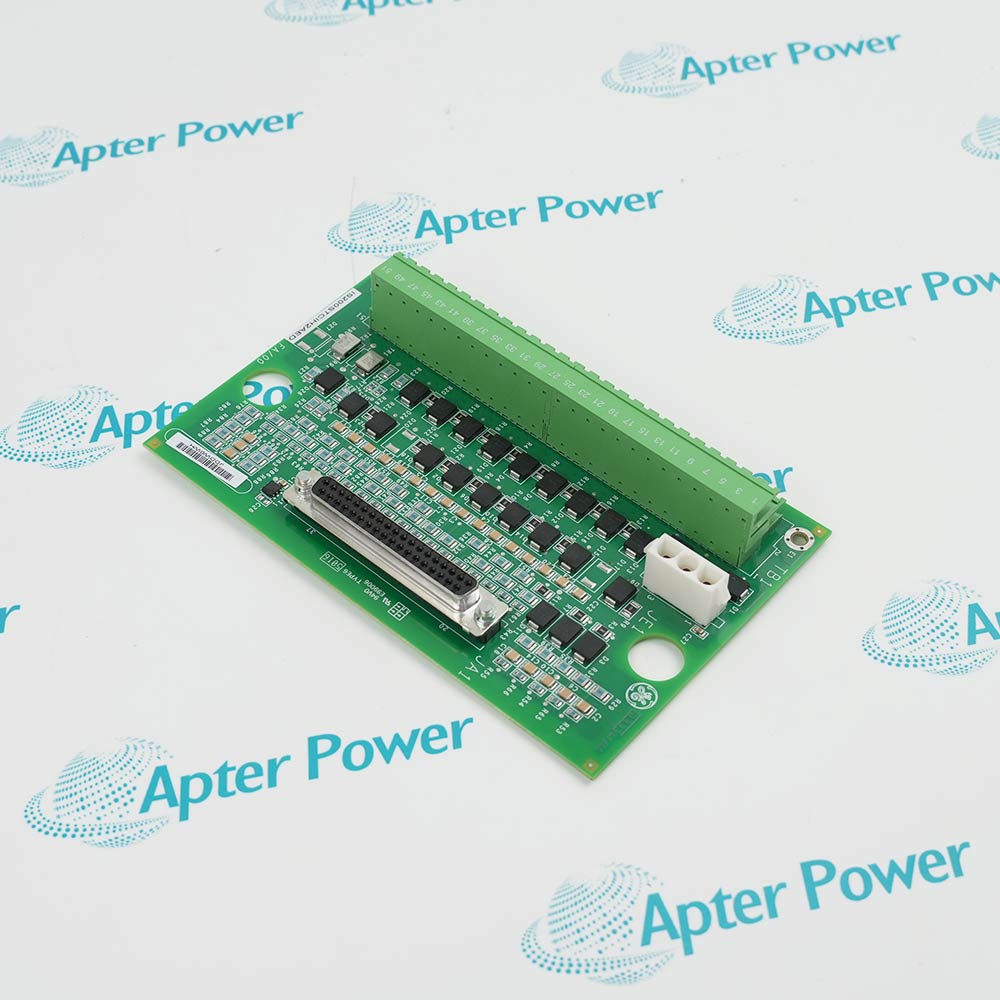
General Electric IS200TSVOH1B is a Mark VI servo terminal board interfacing valve actuators, LVDT feedback, pulse-rate sensors, and VSVO control channels.
In Stock
Ships by Wednesday, October 28
Fast Shipping Available
Get a quick price for IS200TSVOH1B
Quantity
*E-mail
Company
*Mobile
*Content
Upload (gif, jpg, jpeg, png, bmp, doc, docx, xls, xlsx, ppt, pdf, csv)

Technical specifications for IS200TSVOH1B

  • Manufacturer:
    General Electric
  • Part Number:
    IS200TSVOH1B
  • Product Family:
    GE Mark VI Gas Turbine Control
  • Product Type:
    Servo Terminal Board
  • Stock:
    1
  • Associated I/O Board:
    VSVO
  • Servo Outputs:
    4 valve actuator channels
  • LVDT Inputs:
    12 position-feedback channels
  • Pulse Rate Inputs:
    8 flow-monitoring channels
  • Pulse Excitation Outputs:
    2 channels
  • System Configurations:
    TMR and simplex
  • Protection Interface:
    Trip and clamp input
  • Tariff Code:
    8538900000
  • Country of origin:
    USA
  • Place of shipment:
    Xiamen,Fujian,China
By purchasing this item, you agree to the Terms & Conditions, ApterPower is not an authorized distributor for listed manufacturers or tradenames and therefore the manufacturer's warranty does not apply. All our products come with ApterPower's 1-year warranty.

More Information

Overview Manuals Servo Matching Command & Feedback Fault Isolation Product Applications

Features:

  • Terminates two electrohydraulic servo-valve output circuits from the Mark VI VSVO board.
  • Accepts six LVDT feedback windings for turbine-valve position measurement.
  • Includes two pulse-rate input circuits with associated field excitation connections.
IS200TSVOH1B joins actuator command and position feedback at the turbine-valve field interface, allowing each servo loop to use its corresponding LVDT signals.

A second TSVO terminal board can extend a VSVO installation from two servo valves to four without changing the function of each individual board.

The pulse-rate circuits are separate from the servo and LVDT paths, so flow-related measurement signals retain their own termination and excitation connections.

Quotation and availability support for General Electric IS200TSVOH1B Servo Terminal Board is available through Apter Power.
General Electric IS200TSVOH1B Servo Terminal Board Manuals, Datasheets, Links Important Notice: Other accessories, manuals, cables, calibration data, software, etc. are not included with this equipment unless listed in the above stock item description. All prices are shown in USD.

Matching IS200TSVOH1B to the installed actuator loop

  • Coil selection: Record the current-range jumper for each servo circuit before removal; the manual provides selections from 10 mA through 120 mA for supported coils.
  • Feedback population: Identify which of the six available LVDT windings belong to each valve rather than assuming every input is used.
  • VSVO connection: Confirm the J3/J5 cable routes and the actual simplex or three-rack TMR connector set.
  • Field baseline: Save stable command, position, excitation, and pulse-rate readings for comparison during recommissioning.

Reading command and feedback together on IS200TSVOH1B

  • Direction check: Valve travel and each LVDT response should change consistently with the requested command; opposite movement points to polarity or channel mapping.
  • Feedback agreement: Compare redundant LVDTs to separate a single-transducer fault from a common mechanical displacement.
  • No-motion condition: A changing command with fixed feedback requires checks of the coil circuit, hydraulic actuator, and linkage before the board is condemned.
  • Pulse-rate separation: Diagnose flow-related pulse inputs independently because they share the assembly but not the servo feedback function.

IS200TSVOH1B fault patterns and the next useful check

  • Valve hunts: Trend command current and all LVDT channels together, then inspect loose feedback wiring or mechanical play.
  • Travel reverses after maintenance: Recheck both servo-coil and LVDT polarity; correcting only one side can leave the loop driving the wrong way.
  • Only one feedback channel is noisy: Measure at the field connection under the approved procedure to decide whether the symptom follows the transducer path.
  • Command disappears during protection action: Verify the documented trip or clamp input before treating current removal as an electronics failure.

Control tasks connected through IS200TSVOH1B

  • Valve positioning: Two servo outputs and their LVDT feedback form the electrical boundary for closed-loop turbine-valve control on each board.
  • Redundant supervision: In TMR service, LVDT signals fan out through the R, S, and T rack connections while the application defines how feedback devices are combined.
  • Flow measurement: Two pulse-rate inputs accept active or magnetic pickup signals without turning them into servo-position channels.
  • Return to service: Commissioning should prove actuator direction, feedback agreement, pulse response, and the required external-trip action.
Description
General Electric IS200TSVOH1B Servo Terminal Board connects Mark VI VSVO servo-control channels with the electrohydraulic actuators that position turbine valves.

One IS200TSVOH1B provides field termination for two servo-valve outputs and six LVDT feedback windings; two terminal boards can be associated with a VSVO installation serving four servo valves.

The same board carries two pulse-rate input circuits used for flow-related measurements and provides their associated field excitation paths.

Servo command, LVDT position feedback, and pulse-rate measurement remain separate signal groups on IS200TSVOH1B, with board-to-controller connections arranged for the installed simplex or TMR architecture.
Alternative Names
IS200-TSVO-H1B IS 200 TSVO H1B GE IS200TSVOH1B GE Mark VI IS200TSVOH1B IS200TSVO H1B IS2O0TSVOH1B IS200TSV0H1B IS200TSVOH18
Technical notes
IS200TSVOH1B combines servo commands, position feedback, and pulse-rate circuits. Trace each path separately before replacing the board.
Exceptional Service

Our Mission

  • 100% Satisfaction

    We believe expertise is priceless. With over 20 years of experience, and top engineers on staff, we can help you solve or avoid problems that threaten your business.
  • Trust Guaranteed

    Not only do we have a vast inventory, our team makes sure every piece of equipment is in working condition. Your purchases are also backed by our Warranty.
  • Expertise

    Time is money, especially when your equipment is down. We work quickly to get your equipment on its way so you can get it back up and running.

FAQS

The following is a list of questions commonly asked by our customers. Please contact us if you have a question about our process that is not answered below.
Why can a valve connected through IS200TSVOH1B move in the wrong direction after maintenance?
Check IS200TSVOH1B servo-coil polarity, command wiring, and LVDT feedback polarity together; correcting only one side can leave the closed loop driving opposite to the intended position.
What should be tested when IS200TSVOH1B shows unstable position feedback even after the terminal board is replaced?
Measure the IS200TSVOH1B LVDT excitation and inspect feedback wiring and shielding, because loss or distortion of the 3.2 kHz, 7 V rms source can mimic board instability.
How should the servo-current selection on IS200TSVOH1B be handled when an actuator is changed?
Set the IS200TSVOH1B jumpers only to the current range required by the documented servo coil, then verify commanded and actual current before enabling normal valve travel.
Can a long servo cable be accepted on IS200TSVOH1B without measuring its loop resistance?
No; for IS200TSVOH1B, confirm the installed cable remains within the documented length guidance and 15-ohm two-way resistance limit so coil-current regulation is not compromised.
Why might IS200TSVOH1B drive a valve closed while the normal control command remains high?
In a simplex arrangement, an external trip reaching IS200TSVOH1B through JD1 or JD2 can operate the K1 clamp path and bias the valve toward closure independently of the normal command.
Which connectors should be compared before moving IS200TSVOH1B between simplex and TMR wiring arrangements?
IS200TSVOH1B uses JR1 for simplex signals and JR1, JS1, and JT1 for TMR fanout, so the replacement wiring must follow the installed redundancy scheme.
What should be isolated when IS200TSVOH1B loses pulse-rate feedback but servo outputs still respond?
Trace the two IS200TSVOH1B pulse-input circuits and their active or passive sensor wiring separately from the servo coils and LVDT channels, then verify the 2 to 20 kHz signal path.