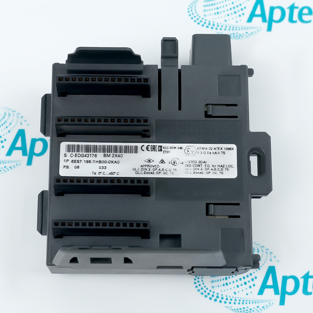
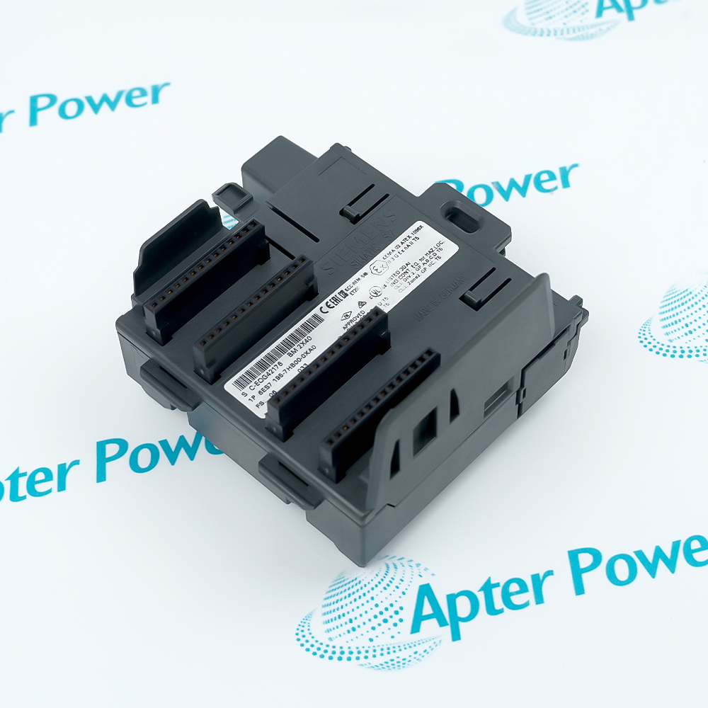
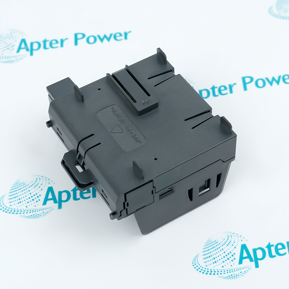
Features:
- Provides two 40 mm active ET 200M module positions.
- Maintains the backplane path independently of a removable I/O module.
- Works with an IM 153 station and the rail used for replacement during operation.
Use 6ES7195-7HB00-0XA0 only with the ET 200M rail intended for active bus modules and reserve space for the two 40 mm module positions.
Install or remove the bus module only while the station is de-energized, even when the finished station supports I/O replacement during operation.
Before startup, close unused backplane positions and confirm that each installed I/O module is seated on the corresponding active-bus connector.
The Siemens 6ES7195-7HB00-0XA0 ET 200M BM 2 x 40 Active Bus Module may still be available for purchase and support from Apter Power beyond End-Of-Life (EOL) by the manufacturer (OEM).
Siemens 6ES7195-7HB00-0XA0 ET 200M BM 2 x 40 Active Bus Module Manuals,Datasheets,Link
Important Notice: Other accessories, manuals, cables, calibration data, software, etc. are not included with this equipment unless listed in the above stock item description. All prices are shown in USD.
How the active bus continues across both module positions
- Incoming bus: The IM 153 side supplies the ET 200M backplane path to the first position.
- First position: The installed module uses the bus connector without terminating the path.
- Second position: The active base carries the same station path into the second 40 mm slot.
- Continuity: Removing one supported I/O module does not open the remaining backplane route.
Keeping the physical and configured station order aligned
- Hardware layout: STEP 7 assigns a module type and address range to each physical position.
- Connector seating: Each I/O module must fully engage the active bus connector for data exchange.
- Position check: The replacement module belongs in the same configured slot, not merely an open position.
- Station restart: A mismatch remains visible to the IM 153 as a configuration or module fault.
What the active base preserves during an approved exchange
- Bus availability: The bus route for neighboring modules remains present during removal.
- Field circuit: The disconnected module no longer exchanges its own field signals.
- Type matching: The inserted unit must match the configured S7-300 module type.
- Diagnostic return: Normal station status returns after seating and configuration agree.
Relating rail, module width and connector position
- Rail choice: The module-change rail provides the mounting geometry required by the active base.
- Position width: Each location is intended for one 40 mm I/O module.
- Base alignment: The 97 mm body positions both active connectors under the module fronts.
- Assembly check: The locking and connector engagement should be verified before power-up.