Bently Nevada 3500 & 3300 Lifecycle Guide for Turbomachinery Protection
About the author
Written by May, Managing Director of Apter Power
May's Facebook:
May has been working at Apter Power for 10 years, where she turns complex power-automation challenges into clear, executable plans.
Drawing on deep product knowledge and field-proven methodologies, she has already supported 2 000+ customers in over 100 countries, maintaining a 96 % satisfaction score.
Turbomachinery protection depends on trust. When signals drift, alarms chatter, or spares get uncertain, the risk moves from a single bad channel to an unplanned trip and a difficult restart. The focus here is practical and field-driven: how 3500 and 3300 architectures behave in real plants, what early aging looks like before failure, how to decide when replacement beats repeated repair, and how to plan spares and compatibility so protection stays credible during a Bently 3300 system upgrade.
Why Bently Nevada 3500 & 3300 Matter for Turbomachinery Protection
A machinery protection system enforces alarm and trip setpoints, so its value depends on one thing: signal integrity. When the measurement chain drifts during startups, load swings, or after maintenance, plants pay for it through nuisance trips, longer fault isolation, and higher exposure during real events. Keeping protection reliable is lifecycle work: controlling the transducer chain, governing configuration changes, and maintaining verified spares.
3500 and 3300 remain central because they must balance availability, integrity, and maintainability on critical rotating assets. A Bently 3300 system upgrade becomes hard to delay once credibility starts consuming hours: repeated callouts to validate channels, growing reliance on temporary substitutions, and a widening gap between documented configurations and what is actually installed.
Typical Architecture of 3500 and 3300 Machinery Protection Systems
Signal integrity problems rarely start in the monitor. In most plants, the fastest way to pinpoint the source is to separate the protection system into practical layers, then verify one layer at a time.
Measurement Chain
For proximity measurements, the chain behaves as a system: probe, extension cable, and Proximitor. Treating these as a matched chain keeps scale factors stable and prevents quiet errors that look like real vibration or thrust movement. This matters most on critical measurements such as thrust and radial vibration, where alarms are tight and response time is limited.
Monitoring and Trip Logic
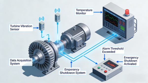
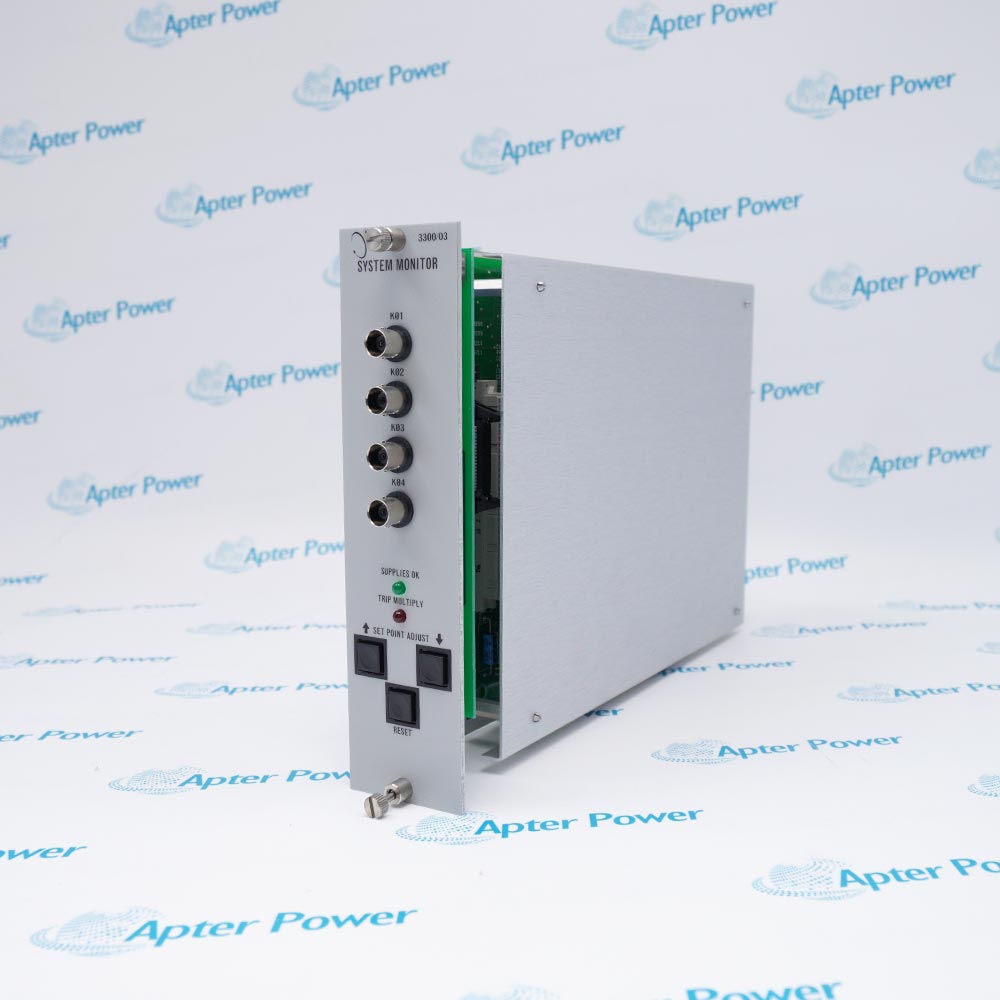
Monitors convert sensor signals into engineering units, apply filtering, and compare against alarm and trip setpoints. Trip outputs and relays then act as the final enforcement point. When a trip debate happens after an event, the monitor configuration and the acceptance test record often become the deciding evidence.
Rack Infrastructure and Interfaces
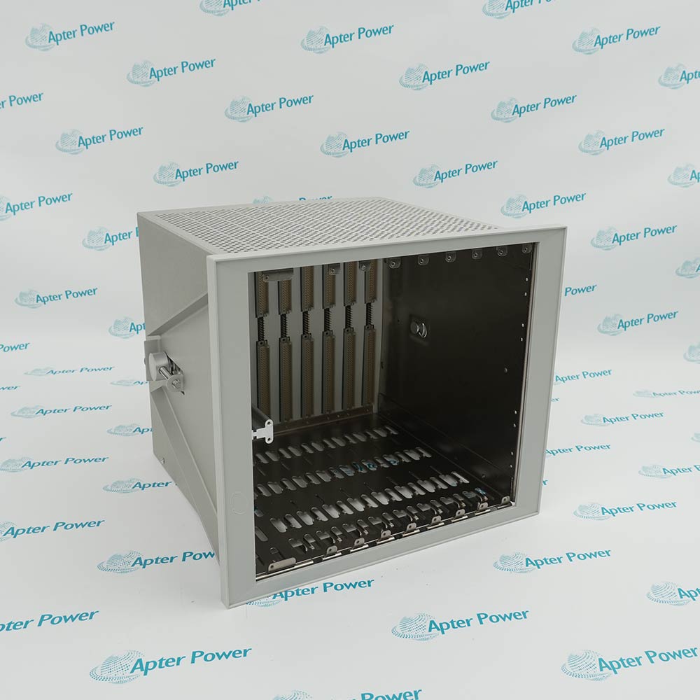
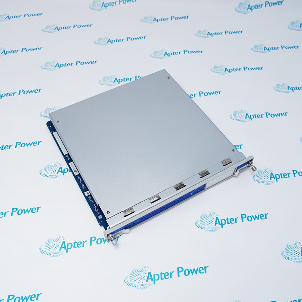
Rack infrastructure provides power distribution, module seating, and backplane connectivity. Interface modules support configuration workflows and diagnostic data movement. This layer affects investigation speed, yet it rarely fixes a protection integrity problem if the upstream measurement chain is compromised.
Plant Integration
Integration covers annunciation, DCS tags, historian mapping, operator response procedures, and test practices. A machinery protection system stays effective when the plant response is consistent, and the alarm philosophy matches how the unit is operated today.
Typical System Configuration Examples (Rack-Level Layouts)
Note: Slot assignments vary by point count, redundancy strategy, and integration method. The examples below are “typical” layouts used for clearer documentation and more professional lifecycle planning.
Example A: 3500 (14-Slot Rack) – Common Turbomachinery Protection Layout
[Left-side dedicated bays]
PS1: 3500/15 Main Power Supply (AC or DC)
PS2: 3500/15 Backup Power Supply (optional; recommended for critical trains)
[Slot 1 – Interface / Configuration boundary]
Slot 1: 3500/22M TDI (Transient Data Interface)
[General slots 2–14 – Grouped by protection function]
Slots 2–3: 3500/42M Vibration Monitor Modules (configured per point count; commonly used for critical radial/casing vibration)
This layout is useful for staged 3300-to-3500 migrations: move the highest-consequence measurements and trip enforcement first, then standardize across outage windows.
PS1: 3500/15 (single supply; add PS2 later if required by criticality)
Slot 6: 3500/92 (optional in phase 1; add when DCS/historian integration is ready)
Remaining slots: reserved for point growth and standardization
What Are the Early Failure Signs and Aging Symptoms in 3500 & 3300 Systems?
Early symptoms usually show up as instability rather than a clear fault. The most useful way to keep troubleshooting MECE is to separate symptoms into three groups: measurement integrity, rack or module behavior, and configuration drift.
Measurement Integrity Symptoms
Common Bently Nevada 3300 XL probe failure symptoms usually appear as instability before a hard fault: slow drift in gap or position at steady load, intermittent OK changes without a process trigger, step changes after a probe or cable replacement, or a higher noise floor that makes trends look rough. After “quick fixes,” mismatched probe, cable, and Proximitor combinations can look stable while scaling is wrong, which then drives the wrong alarms during startups and load swings.
Rack and Module Aging Symptoms
Aging in the rack is often repeatable. If a channel alarms again after a clean repair, treat it as a warning sign. Faults that follow the module point to the module or input stage; faults that stay with the slot point to terminations, backplane contacts, power distribution, or wiring condition. Slot-related behavior is a common aging pattern because connection integrity degrades gradually and worsens after handling.
Configuration Drift Symptoms
The rack can be healthy, while protection behaves poorly if the operating envelope changes. Alarms that became “normal” during startup, trips during routine load transitions, or setpoints that no longer match current modes after rerates or control changes are typical signs. Configuration drift is also one of the fastest ways a machinery protection system loses operator trust.
Symptom-to-First-Check Table
When to Replace: A Practical Lifecycle Plan
Repeated repairs can keep a rack running, but they also increase hidden costs: longer troubleshooting, more temporary substitutions, and higher trip exposure. A practical lifecycle plan defines clear triggers for replacement and migration before the next forced outage.
Replacement Triggers That Matter
A repair remains reasonable when the failure is isolated, the root cause is clear, and post-repair behavior stays stable. Replacement or migration becomes the better option when one or more triggers appear:
1. Repeatability across cycles: A channel that returns to alarm after a clean repair is rarely “bad luck.” Repeated events often indicate aging terminations, backplane wear, or recurring measurement chain mistakes.
2. Spares risk becomes structural: A cabinet with parts is not the same as a reliable spares path. Risk rises when restoration depends on unverified stock, uncertain replenishment, or mixed substitutions to “make it work.”
3. Verification and documentation fall behind reality: If the plant can’t confidently prove chain integrity, setpoint intent, and trip path behavior, the machinery protection system becomes hard to defend after an event.
Repair, Replace, Or Migrate
Repair fits best when one failure mode is proven, and spares are stable for that exact configuration.
Replace fits best when channel integrity remains uncertain after repairs or when spares risk forces repeated improvisation.
Migrate fits best when multiple channels show aging patterns or when the spares situation makes long-term support unpredictable.
A Bently 3300 system upgrade is often the practical middle ground: reduce risk first on the highest consequence measurements, then standardize around the new baseline as outage windows allow.
Migration Scope That Works in Outage Windows
A workable Bently 3300 to 3500 system migration strategy stays explicit about scope, commissioning time, and documentation. Start with critical trains and critical measurements, align rack-level work with windows that allow verification, then lock the alarm philosophy so operators do not inherit inconsistent protection behavior across units.
How to Plan Spares for Bently 3500/3300, Probes, and Cables
A spare plan should restore protection quickly without changing measurement behavior. The steps below define what to stock, how to size it, and how to verify it before it goes on the shelf.
Step 1: Define “Restored” for Each Critical Train
Write a simple restoration standard: the machinery protection system must return to valid measurements and enforce alarms and trips without temporary substitutions. This prevents a common failure mode where a channel is “back online” but scaled incorrectly.
Step 2: Build the Spares Model in Three Buckets
Protection-critical rack items: Monitors and rack items that determine protection availability and trip enforcement.
Measurement chain sets: Stock complete proximity sets as a matched group. This is the safest way to restore a channel without changing scaling behavior.
Diagnostic and interface items: These speed post-trip analysis and troubleshooting, yet they come after protection integrity is secured.
This structure also answers the operational question behind Bently Nevada 3500/42M monitor spare parts availability. Instead of hunting part numbers under pressure, map the monitor types used across critical assets and stock by criticality tier.
Step 3: Set Quantity Rules That Survive Budget Review
Quantity rules are simple: stock one spare for each common monitor type on critical trains, keep one complete proximity chain set per common probe family and cable length on critical measurements, and add more only when site history justifies it.
Step 4: Verify Spares Before Shelving
A spare that fails at installation time increases outage risk. Verification includes identity confirmation, basic bench checks, and recording what pairing and configuration the spare is intended to support.
3300 XL Probes, Cables, and Proximitor Modules Compatibility Guide
Compatibility errors often look like machine problems. Keeping the probe, extension cable, and Proximitor pairing consistent protects scaling, reduces false alarms, and prevents wasted troubleshooting time.
Compatibility Rules
Rule 1: Control the chain as a system. Treat probe, extension cable, and Proximitor as a defined set. A partial replacement often introduces scaling changes that look like a machine problem.
Rule 2: Keep families separated and documented. Sites that carry both XL and non-XL populations should control them as distinct baselines. Mixing parts creates hidden performance limits and complicates alarm interpretation.
Rule 3: Match mechanical constraints without changing behavior. Clearance, mounting style, and target geometry matter. Solving a clearance issue with a “fits in the hole” substitution can quietly change sensitivity and linear range.
High-Risk Mismatch Scenarios
A small number of scenarios cause a large share of field confusion:
emergency substitutions during outages that bypass normal documentation
cable length changes that alter the intended system configuration
mixed-family swaps that keep OK status green while shifting scale factors
Acceptance Checks After Replacement
After any chain replacement, the channel should be treated as a protection channel during return-to-service:
Stable OK behavior at known operating conditions
Gap range within the expected window for that machine
Trends that remain stable during steady operation and respond sensibly during controlled transients
Compatibility discipline makes a Bently 3300 system upgrade predictable. Without it, each maintenance event introduces new variability and new debates.
Partner with Lifecycle Experts to Secure Your Turbomachinery Protection
Lifecycle support reduces uncertainty in three places: measurement chain discipline, spares quality, and commissioning consistency. The strongest programs keep configurations documented, verify parts before they go on the shelf, and align upgrade scope with outage reality. That approach improves response speed during alarms, shortens troubleshooting time, and lowers nuisance trip risk. It also makes a Bently 3300 to 3500 system migration strategy repeatable, so each phase ends in a stable baseline that operations can trust.
FAQs about Protection System Reliability
Q1: Do trip relays and shutdown outputs need periodic proof testing?
Yes. Proof testing confirms the complete trip path works under real load, including relay contacts, wiring, and shutdown circuitry. Align intervals with unit criticality and outage cadence, then record results for auditability and to spot degrading response times.
Q2: Can protection data be sent to a historian without increasing trip risk?
Yes. Use read-only paths and network segregation so data collection cannot write back to the rack. Keep configuration access restricted, log all changes, and route diagnostics through controlled interfaces approved by reliability and controls engineering.
Q3: Should alarm and trip setpoints be revisited after a rerate or mechanical retrofit?
Yes. Rerates, bearing changes, seal upgrades, and control tuning can shift vibration response. Update the alarm philosophy through MOC, validate using startup and load-transition observations, and document the rationale so future events are judged against current intent.
Q4: Are third-party-repaired modules acceptable for protection service?
Yes, with qualification. Require traceability, functional verification on representative inputs, burn-in where practical, and configuration compatibility checks. Treat repaired modules as conditional until they demonstrate stable behavior across at least one operating cycle on a noncritical position.
Q5: What documentation most reduces troubleshooting time during outages?
A current channel list, wiring diagrams, configuration backups, alarm philosophy, loop-check records, and a transducer chain register by measurement point. Keep revision control strict, store it where maintenance can access it offline, and update after every change.
Optimizing Turbomachinery Protection Through Lifecycle Spare Management
Key Scenarios for Risk Reduction and Operational Efficiency
Effective turbomachinery protection is about more than alarms and trips—it is about reducing operational uncertainty and enabling proactive maintenance planning. Unexpected downtime, spares shortages, or maintenance improvisation can escalate costs and compromise plant reliability. This guide explores strategies to maximize protection system value while controlling lifecycle costs:
Risk Management Through Strategic Spares and System Planning
Industrial plants face multiple layers of risk: sudden equipment trips, delayed fault isolation, and inconsistent maintenance responses. By planning spares portfolios around critical assets, including Bently Nevada 3500 and 3300 monitors, probes, and related interface modules, operators can mitigate these risks before failures occur. For example, stocking complete proximity measurement sets and verified 3500/42 vibration monitors ensures that replacements do not alter system behavior. The practical effect is a measurable reduction in unplanned shutdowns, faster recovery after incidents, and greater confidence in system reliability across all operating conditions.
Cost and Efficiency Gains Through Lifecycle-Focused Decisions
Lifecycle-focused spare parts management allows plants to make data-driven repair, replacement, or migration decisions. Monitoring usage patterns and maintenance history helps identify when recurring repairs become costlier than planned replacements, or when phased upgrades from 3300 to 3500 systems improve long-term availability. Adopting this approach delivers concrete benefits: lower maintenance labor costs, fewer emergency procurements, optimized inventory investment, and smoother integration of system upgrades. It also ensures that operational teams can prioritize critical maintenance without compromising overall production continuity.














Leave Your Comment