Ask our team:
  • Phone: +86 181 0690 9650
  • E-Mail info@apterpower.com
  • Lifecycle status

    Active / Available from OEM
    Request IS200CABPG1B quotations, official English documents and control-rack configuration assistance from Apter Power.

IS200CABPG1B

/ 4.9
1001 reviews | Need a Specific Revision?
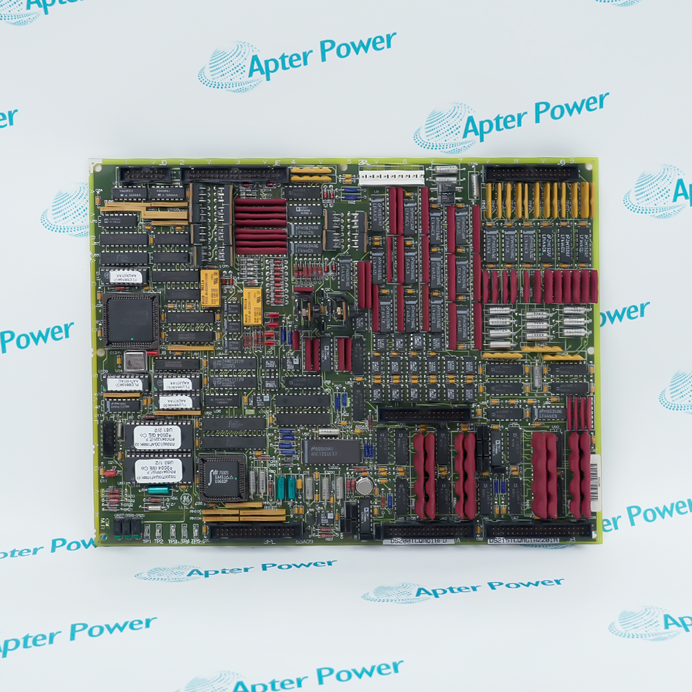
General Electric IS200CABPG1B is an Innovation Series control assembly backplane that interconnects rack boards, external drive signals and power interfaces.
In Stock
Ships by Tuesday, September 29
Fast Shipping Available
Get a quick price for IS200CABPG1B
Quantity
*E-mail
Company
*Mobile
*Content
Upload (gif, jpg, jpeg, png, bmp, doc, docx, xls, xlsx, ppt, pdf, csv)

Technical specifications for IS200CABPG1B

  • Manufacturer:
    General Electric
  • Part Number:
    IS200CABPG1B
  • Product Family:
    GE Mark V/VI Driver Board
  • Product Type:
    Control Assembly Backplane Board
  • Stock:
    1
  • System:
    Innovation Series Drive
  • Board Construction:
    Multilayer printed wiring board
  • Power Source:
    Single IS200HFPA board
  • External Interfaces:
    J1-J12
  • Backplane Interfaces:
    J13-J21
  • Ground/Common Connectors:
    E1-E4
  • ISBus Interfaces:
    J11 and J12 local/system ports
  • Indicators and Fuses:
    None
  • Tariff Code:
    8537101190
  • Country of origin:
    USA
  • Place of shipment:
    Xiamen,Fujian,China
By purchasing this item, you agree to the Terms & Conditions, ApterPower is not an authorized distributor for listed manufacturers or tradenames and therefore the manufacturer's warranty does not apply. All our products come with ApterPower's 1-year warranty.

More Information

Overview Manuals Board Population External Interfaces Power & Grounding Connector Map

Features:

  • Interconnects the control boards fitted to an Innovation Series rack.
  • Combines external I/O, keypad, meter and ISBus interfaces on one backplane.
  • Separates chassis-ground and control-common paths through dedicated stab connectors.
The installed board set changes with drive power level and control architecture, so the backplane supports several defined rack populations.

Front-facing connectors concentrate cabinet wiring while J13-J21 route signals internally to the boards occupying the six rack positions.

Two isolated ac feeds from the HFPA supply the assembly, and E1-E4 provide the cabinet grounding and common reference points.

Record the board population, connector positions and grounding points before selecting General Electric IS200CABPG1B for a control assembly.
General Electric IS200CABPG1B Control Assembly Backplane Board Manuals,Datasheets,Link Important Notice: Match J1-J21 cable positions and the populated rack boards to the installed IS200CABPG1B arrangement.

Rack positions supported by the backplane

  • Slot One: BAIA connects through J13 and J17.
  • Power Slot: RAPA receives its backplane link at J14.
  • Control Slot: ACL or GBIA/PBIA can occupy the shared position.
  • Bridge Slots: BIC and BPI or FOSA boards use paired backplane connectors.

Cabinet-facing signal connections

  • User I/O: J6 carries higher-voltage signals and J7 carries lower-voltage signals.
  • Meters: J8 supports as many as four front-panel meters.
  • Service Tool: J9 provides the diagnostic and configuration connection.
  • Keypad: J10 links the front-panel keypad to power and serial signals.

Supply and reference paths

  • Main Feed: The HFPA supplies 48 V ac through a shielded pair.
  • Auxiliary Feed: A separate isolated pair carries 17 V ac.
  • Chassis Ground: E1 and E2 connect GND to the rack chassis.
  • Control Common: E3 and E4 tie the backplane to cabinet CCOM.

Local and system ISBus ports

  • Local ISBus: J11A carries isolated transmit, receive and 24 V power.
  • Local Transmit: J11B provides an isolated transmit-only path.
  • System ISBus: J12A supports the extended transmit, receive and power interface.
  • System Transmit: J12B carries the matching isolated transmit signal.
Description
Within an Innovation Series drive rack, General Electric IS200CABPG1B serves as the Control Assembly Backplane. This multilayer printed wiring board joins the inserted control and interface boards while presenting their required external signal connections.

Board population on IS200CABPG1B varies with drive power level and application. The backplane provides positions for BAIA, RAPA, BIC and BPI or FOSA boards, plus an optional DSPX and a shared slot for an ACL board or GBIA/PBIA module.

External wiring reaches IS200CABPG1B through J1-J12 for functions that include contactor circuits, user I/O, meters, configuration tools, a keypad and local or system ISBus links. Nine backplane connectors J13-J21 distribute those signals to the installed boards rather than terminating each board separately at the cabinet boundary.

A single HFPA board supplies IS200CABPG1B through isolated 48 V ac and 17 V ac paths. E1-E4 establish chassis ground and control-cabinet common connections, while the backplane itself has no LEDs, fuses, adjustable hardware or user testpoints.
Alternative Names
IS 200 CABP G1B GE IS200CABPG1B IS200-CABP-G1B Control Backplane IS200CABPG1B General Electric IS200CABPG1B Innovation Series CABP G1B IS200CABP G1B IS200CABPGIB
Technical notes
General Electric IS200CABPG1B distributes rack, user-I/O, ISBus and HFPA connections across the Innovation Series control assembly.
Exceptional Service

Our Mission

  • 100% Satisfaction

    We believe expertise is priceless. With over 20 years of experience, and top engineers on staff, we can help you solve or avoid problems that threaten your business.
  • Trust Guaranteed

    Not only do we have a vast inventory, our team makes sure every piece of equipment is in working condition. Your purchases are also backed by our Warranty.
  • Expertise

    Time is money, especially when your equipment is down. We work quickly to get your equipment on its way so you can get it back up and running.

FAQS

The following is a list of questions commonly asked by our customers. Please contact us if you have a question about our process that is not answered below.
How should the installed board set be checked before ordering IS200CABPG1B?
Compare the IS200CABPG1B rack population with the BAIA, RAPA, BIC, BPI/FOSA and optional DSPX or ACL/GBIA/PBIA positions used by the drive.
Which IS200CABPG1B connectors need extra attention when separating high- and low-voltage I/O?
On IS200CABPG1B, J6 is assigned to signals typically above 50 V, while J7 handles signals typically below 50 V.
Can IS200CABPG1B support local and extended ISBus wiring at the same time?
IS200CABPG1B provides local ISBus ports at J11A/J11B and system or extended interfaces at J12A/J12B; use the port defined by the drive layout.
Why should every cable location be recorded before removing IS200CABPG1B?
The twelve external connectors on IS200CABPG1B serve different contactor, I/O, meter, tool, keypad and ISBus functions, so position labels prevent cross-connection.
What confirms the power arrangement for IS200CABPG1B?
Check that IS200CABPG1B is fed from one IS200HFPA board with separate isolated 48 V ac and 17 V ac cable pairs and that E1-E4 retain their ground/common assignments.