Ask our team:
  • Phone: +86 181 0690 9650
  • E-Mail info@apterpower.com
  • Lifecycle status

    Discontinued / Obsolete by OEM
    Apter Power provides DS200TCQEG1A quotes, official data and Mark V LM matching support.

DS200TCQEG1A

/ 4.9
1001 reviews | Need a Specific Revision?
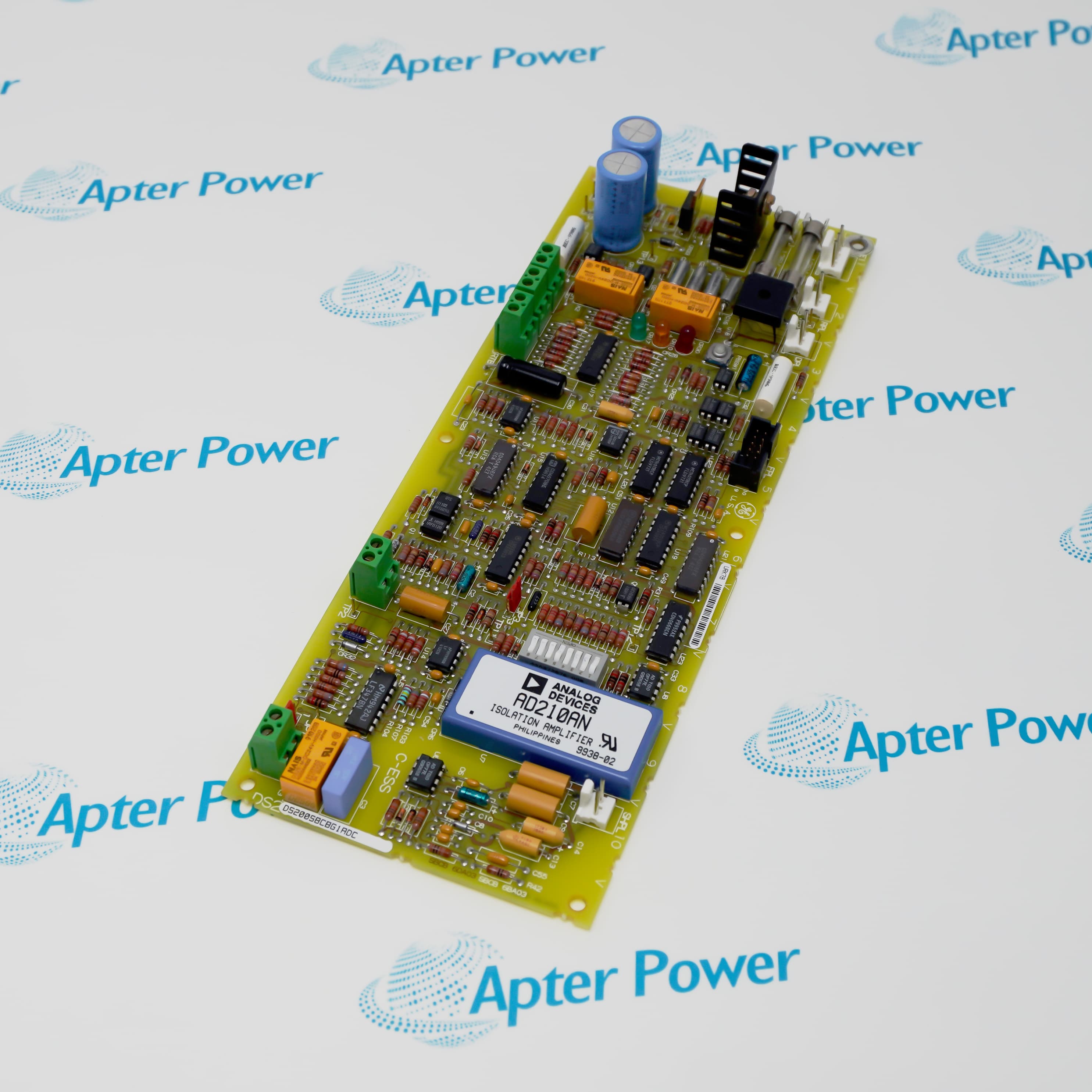
General Electric DS200TCQEG1A is a SPEEDTRONIC Mark V LM6000 I/O processor board that conditions added analog, vibration, position, temperature and speed signals.
In Stock
Ships by Tuesday, September 29
Fast Shipping Available
Get a quick price for DS200TCQEG1A
Quantity
*E-mail
Company
*Mobile
*Content
Upload (gif, jpg, jpeg, png, bmp, doc, docx, xls, xlsx, ppt, pdf, csv)

Technical specifications for DS200TCQEG1A

  • Manufacturer:
    General Electric
  • Part Number:
    DS200TCQEG1A
  • Product Family:
    SPEEDTRONIC Mark V
  • Product Type:
    LM6000 I/O Processor Board
  • Stock:
    1
  • Board Designation:
    TCQE
  • Core Location:
    R1 core, location 3
  • Data Bus:
    3PL to STCA and TCQA
  • Position Inputs:
    LVDT/LVDR
  • Current Outputs:
    Two selectable 4–20 mA or 20–200 mA channels
  • Sensor Paths:
    RTD, vibration, proximity and pulse-rate inputs
  • Tariff Code:
    8537101190
  • Country of origin:
    USA
  • Place of shipment:
    Xiamen,Fujian,China
By purchasing this item, you agree to the Terms & Conditions, ApterPower is not an authorized distributor for listed manufacturers or tradenames and therefore the manufacturer's warranty does not apply. All our products come with ApterPower's 1-year warranty.

More Information

Overview Manuals Signal Routes Sensor Channels Output Control Board Setup

Features:

  • Scales the additional analog I/O assigned to the LM6000 control arrangement.
  • Combines position, temperature, vibration and pulse-rate processing on one R1-core board.
  • Returns conditioned data to the STCA over the Mark V 3PL bus.
DS200TCQEG1A occupies location three of the R1 core and works between the TBQE termination board and the Mark V control sequence.

Separate connector paths preserve the identity of shaft-speed, LVDT/LVDR, RTD and vibration channels before the values enter the I/O engine.

Hardware jumpers select the current-output range, while operator-interface constants define how the monitored channels are interpreted.

The General Electric DS200TCQEG1A LM6000 I/O Processor Board may still be available for purchase and support from Apter Power beyond End-Of-Life (EOL) by the manufacturer (OEM).
General Electric DS200TCQEG1A LM6000 I/O Processor Board Manuals, Datasheets, Links Important Notice: Other accessories, manuals, cables, calibration data, software, etc. are not included with this equipment unless listed in the above stock item description. All prices are shown in USD.

Connector-Level Paths

  • JLL Interface: Carries LVDT/LVDR and RTD inputs while returning the two current outputs to TBQE.
  • JQQ Interface: Receives LM vibration, proximity-vibration and selected pulse-rate feedback.
  • Shaft Feedback: JJQ reads high- and low-pressure shaft-speed signals from PTBA.
  • Control Transfer: 3PL passes conditioned board data to STCA through the R1 analog bus.

Processed Measurement Groups

  • Position: LVDT and LVDR feedback is scaled for the control-sequence program.
  • Temperature: RTD resistance changes are converted into conditioned temperature signals.
  • Vibration: LM and proximity-vibration inputs use separate signal paths.
  • Speed: Magnetic-pickup and TTL pulse channels support shaft-speed measurement.

Selectable Current Functions

  • Channel Count: Two milliamp outputs are provided on the TCQE board.
  • Normal Range: Each channel can be configured for a 4–20 mA span.
  • High Range: Hardware selection also permits a 20–200 mA maximum range.
  • Field Route: Both outputs leave through JLL for the TBQE termination board.

Hardware and Software Boundaries

  • Output Enable: JP4 and JP6 configure the two current-output circuits.
  • Range Choice: JP5 and JP7 select 20 mA or 200 mA maximum current.
  • Stall Timer: JP8 controls the board stall-timer function.
  • I/O Constants: Channel types and scaling values are entered in the operator-interface configuration editor.
Description
General Electric DS200TCQEG1A is the TCQE LM6000 I/O processor board installed in location three of the SPEEDTRONIC Mark V R1 core. The board expands the analog signal set used by the LM control architecture rather than serving as a field terminal assembly.

Through JLL and JQQ, General Electric DS200TCQEG1A receives LVDT/LVDR position feedback, RTD temperature measurements, LM vibration, proximity-vibration and pulse-rate signals from TBQE. JJQ also brings the high- and low-pressure shaft-speed paths from PTBA into the processor board.

Two current channels on General Electric DS200TCQEG1A drive selectable 4–20 mA or 20–200 mA outputs back through JLL. Position, temperature and vibration values are scaled and conditioned before 3PL transfers the processed data to STCA for the control sequence.

Configuration of General Electric DS200TCQEG1A separates hardware range selection from software I/O constants. JP4 and JP6 enable the two current outputs, JP5 and JP7 select their maximum range, and the remaining channel definitions are entered through the Mark V I/O Configuration Editor.
Alternative Names
GE DS200TCQEG1A DS200TCQE-G1A DS200 TCQE G1A DS 200 TCQE G1A TCQE G1A LM I/O Board Mark V DS200TCQEG1A General Electric TCQE G1A DS2O0TCQEG1A
Technical notes
General Electric DS200TCQEG1A is the R1-core TCQE board for LM6000 analog, vibration, position, temperature and pulse-rate processing.
Exceptional Service

Our Mission

  • 100% Satisfaction

    We believe expertise is priceless. With over 20 years of experience, and top engineers on staff, we can help you solve or avoid problems that threaten your business.
  • Trust Guaranteed

    Not only do we have a vast inventory, our team makes sure every piece of equipment is in working condition. Your purchases are also backed by our Warranty.
  • Expertise

    Time is money, especially when your equipment is down. We work quickly to get your equipment on its way so you can get it back up and running.

FAQS

The following is a list of questions commonly asked by our customers. Please contact us if you have a question about our process that is not answered below.
Why can one current loop remain inactive after General Electric DS200TCQEG1A is installed?
On General Electric DS200TCQEG1A, check the matching JP4 or JP6 output-enable position, the JP5 or JP7 range selection and the JLL field route.
Which connections should be traced when DS200TCQEG1A loses shaft-speed feedback?
Trace DS200TCQEG1A from PTBA through JJQ for the high- and low-pressure speed paths, then verify the related I/O constant.
How does General Electric DS200TCQEG1A separate position and vibration signals?
General Electric DS200TCQEG1A receives position and RTD channels through JLL, while JQQ carries the LM and proximity-vibration inputs.
What must match before a DS200TCQEG1A current-output range is changed?
The DS200TCQEG1A hardware jumper setting and the configured channel range must agree before the loop is returned to service.
Where should DS200TCQEG1A processed values appear in the Mark V signal path?
After conditioning on DS200TCQEG1A, the values travel through 3PL to STCA for use by the control sequence.
Can General Electric DS200TCQEG1A be treated as the field termination board?
No. General Electric DS200TCQEG1A is the processor board in R1; TBQE is the associated termination point for most of its field circuits.