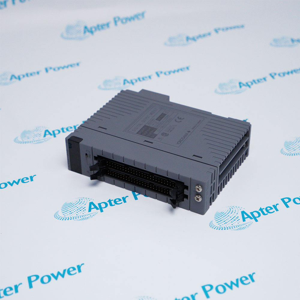
VF702 S1
VF702 S1
VF702 S1
VF702 S1
VF702 S1
VF702 S1
Ask our team:
  • Phone: +86 181 0690 9650
  • E-Mail info@apterpower.com
  • Lifecycle status

    Active / Available from OEM
    Apter Power supports VF702 S1 quotations, English technical information, and CENTUM interface selection.

VF702 S1

/ 4.9
1001 reviews | Need a Specific Revision?
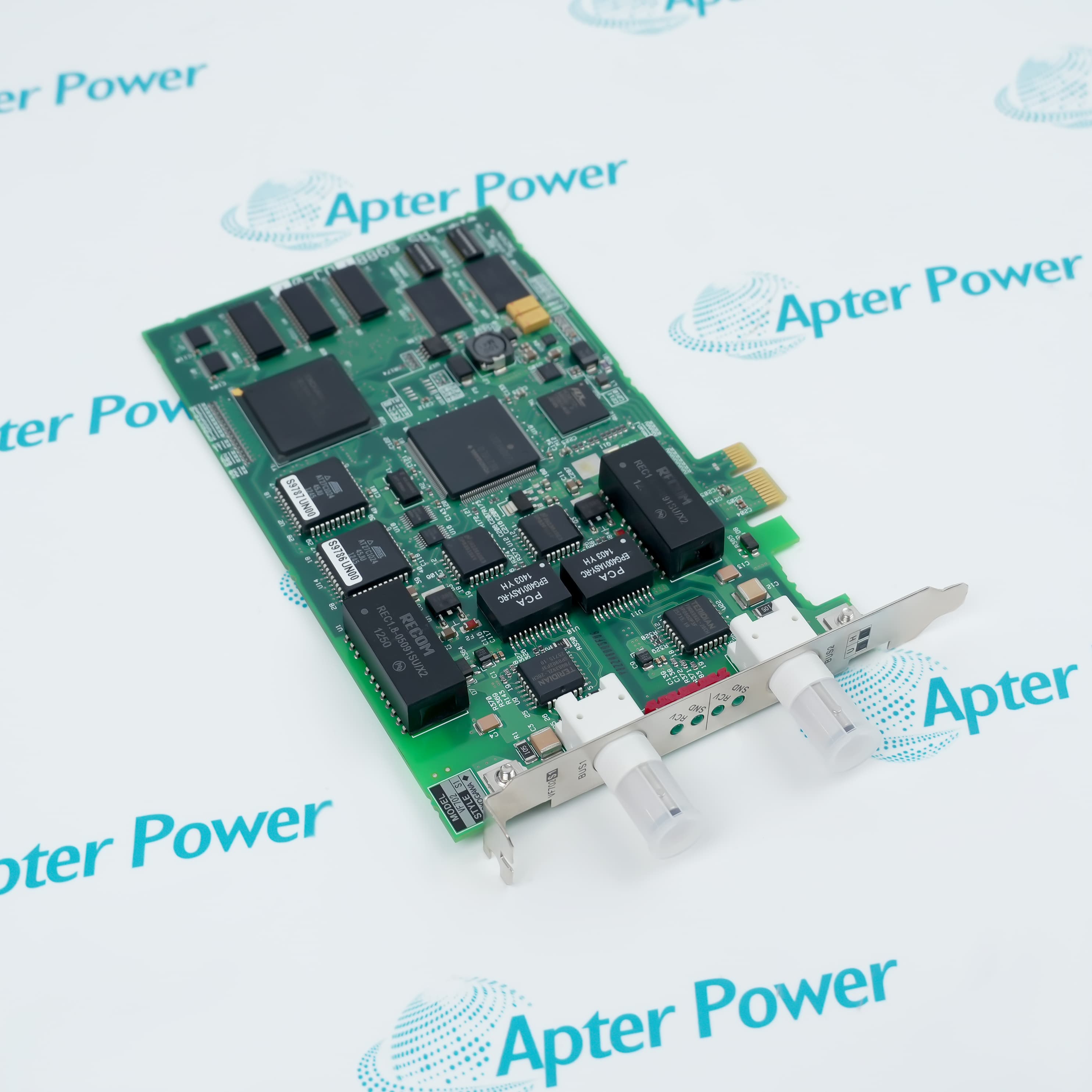
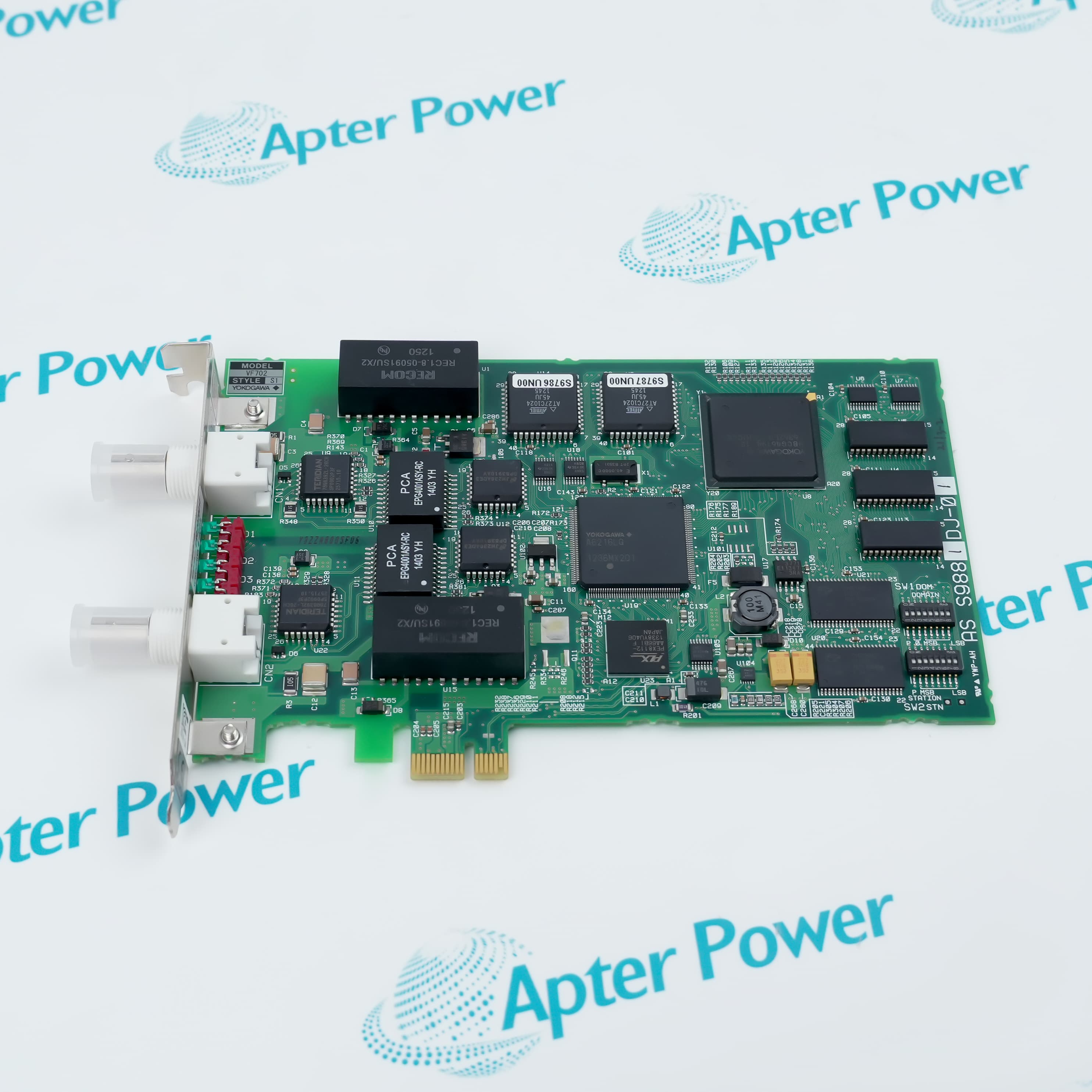
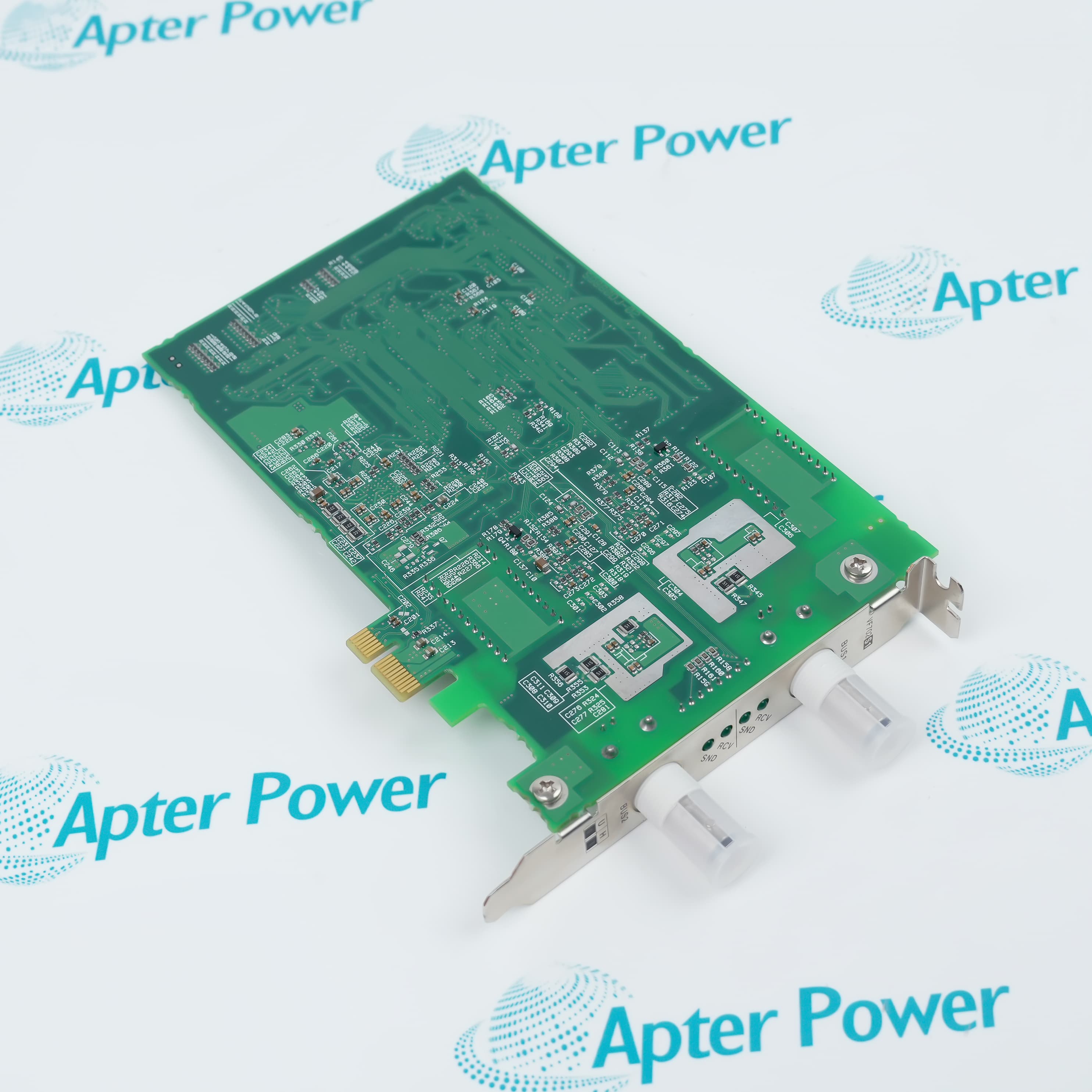
YOKOGAWA VF702 S1 is a PCI Express V net control bus interface card that connects a PC/AT-compatible SENG to a dual-redundant control bus.
In Stock
Ships by Tuesday, September 29
Fast Shipping Available
Get a quick price for VF702 S1
Quantity
*E-mail
Company
*Mobile
*Content
Upload (gif, jpg, jpeg, png, bmp, doc, docx, xls, xlsx, ppt, pdf, csv)

Technical specifications for VF702 S1

  • Manufacturer:
    Yokogawa
  • Part Number:
    VF702 S1
  • Product Family:
    Centum CS-Centum VP
  • Product Type:
    Control Bus Interface Card
  • Stock:
    1
  • Host Interface:
    PCI Express
  • Control Bus:
    V net
  • V net Ports:
    2
  • Network Arrangement:
    Dual-redundant bus
  • Cable Connector:
    BNC with T connector
  • Host Station:
    PC/AT-compatible SENG
  • Address Setting:
    Domain and station DIP switches
  • Status Indication:
    RCV and SND LEDs
  • Weight:
    0.15 kg
  • Estimated shipping dimensions:
    2.2x12.6x19.4cm
  • Tariff Code:
    8537101190
  • Country of origin:
    Japan
  • Place of shipment:
    Xiamen,Fujian,China
By purchasing this item, you agree to the Terms & Conditions, ApterPower is not an authorized distributor for listed manufacturers or tradenames and therefore the manufacturer's warranty does not apply. All our products come with ApterPower's 1-year warranty.

More Information

Overview Manuals Connectivity Addressing Installation Standards

Features:

  • PCI Express interface for a PC/AT-compatible CENTUM system engineering station.
  • Two coaxial V net ports maintain the control bus's redundant path arrangement.
  • On-card switches assign the required domain and station identity.
VF702 S1 bridges the engineering computer and V net without merging the host-side PCI Express connection with the field-side coaxial network.

Both V net channels of VF702 S1 are presented as separate BNC connections, preserving the paired network topology used by the control bus.

Front-panel receive and send indicators make VF702 S1 traffic activity visible at the interface card, while the S1 style identifies the marine-standard configuration.

The YOKOGAWA VF702 S1 V net Control Bus Interface Card is available for purchase and support from Apter Power.
YOKOGAWA VF702 S1 V net Control Bus Interface Card Manuals,Datasheets,Link Important Notice: Other accessories, manuals, cables, calibration data, software, etc. are not included with this equipment unless listed in the above stock item description. All prices are shown in USD.

V net and host-side links

  • Computer bus: The host connection uses a PCI Express slot in the system engineering station.
  • Control network: Two independent interfaces attach the card to the redundant V net.
  • Physical media: Each V net route uses coaxial cable and a BNC T connector.
  • Bus continuation: The T connection accepts the preceding and following network segments or an end terminator.

Domain and station identity

  • Domain setting: A dedicated switch bank selects the V net domain number.
  • Station setting: A separate switch bank defines the system engineering station number.
  • Pre-start setup: Address switches are set before the station enters normal network operation.
  • Identity boundary: The configured domain and station pair distinguishes the host on V net.

Card and network placement

  • Host format: The card fits a PC/AT-compatible SENG equipped with PCI Express.
  • Network pairing: Both redundant V net cables are connected to their corresponding interfaces.
  • Activity check: RCV and SND indicators provide a local view of receive and transmit traffic.
  • Segment endpoint: A terminator is installed on the open side of the T connector when the card occupies a bus end.

S1 compliance distinction

  • Style code: S1 identifies a defined hardware style within the VF702 card family.
  • Marine conformity: The S1 configuration is the VF702 style specified to meet marine standards.
  • Model control: The complete VF702 S1 designation is required when confirming this compliance variant.
  • Interface basis: Compliance applies to the PCI Express V net interface configuration represented by the S1 code.
Description
YOKOGAWA VF702 S1 is a V net control bus interface card for a PC/AT-compatible system engineering station in the CENTUM control environment. Installed in a PCI Express slot, the card exchanges engineering-station traffic with the dual-redundant V net network.

Two independent V net ports on YOKOGAWA VF702 S1 form the paired bus connection. Each coaxial route attaches through a BNC T connector, allowing the interface to sit between the preceding and following stations or to accept termination at the end of a segment.

Network identity is established directly on YOKOGAWA VF702 S1 through separate domain-number and station-number DIP switches. RCV and SND indicators expose receive and transmit activity so the two directions can be checked at the card during installation and operation.

The S1 style code identifies YOKOGAWA VF702 S1 as the VF702 configuration that conforms to the specified marine standards. Its host-side PCI Express interface and V net-side coaxial ports keep computer-bus integration separate from the redundant control-network connections.
Alternative Names
VF702 S1 VF702-S1 VF702S1 YOKOGAWA VF702-S1 Yokogawa Electric VF702 S1 CENTUM VF702 S1 VF702 Style S1 VF7O2 S1
Technical notes
YOKOGAWA VF702 S1 provides a PCI Express host interface and two coaxial ports for dual-redundant V net communication.
Exceptional Service

Our Mission

  • 100% Satisfaction

    We believe expertise is priceless. With over 20 years of experience, and top engineers on staff, we can help you solve or avoid problems that threaten your business.
  • Trust Guaranteed

    Not only do we have a vast inventory, our team makes sure every piece of equipment is in working condition. Your purchases are also backed by our Warranty.
  • Expertise

    Time is money, especially when your equipment is down. We work quickly to get your equipment on its way so you can get it back up and running.

FAQS

The following is a list of questions commonly asked by our customers. Please contact us if you have a question about our process that is not answered below.
How should YOKOGAWA VF702 S1 connect to a redundant V net?
Use both coaxial V net ports on YOKOGAWA VF702 S1, keeping the two bus routes separate and attaching each route through its own BNC T connector.
Where are the network addresses set on YOKOGAWA VF702 S1?
Domain and station numbers are selected with the dedicated DIP switches on YOKOGAWA VF702 S1 before the interface joins the V net.
What do the RCV and SND indicators on YOKOGAWA VF702 S1 show?
On YOKOGAWA VF702 S1, RCV reports incoming bus activity and SND reports transmitted traffic, providing a direct check of communication direction.
Which host computer arrangement accepts YOKOGAWA VF702 S1?
YOKOGAWA VF702 S1 is designed for a PC/AT-compatible system engineering station with an available PCI Express slot.
Why is the S1 code important for YOKOGAWA VF702 S1?
The S1 style code distinguishes YOKOGAWA VF702 S1 as the VF702 configuration specified to conform to the applicable marine standards.
How is an end-of-line V net cable handled with YOKOGAWA VF702 S1?
At a segment end, the coaxial route connected to YOKOGAWA VF702 S1 is terminated at the BNC T connection instead of continuing to another station.

Product Browsing History