Ask our team:
  • Phone: +86 181 0690 9650
  • E-Mail info@apterpower.com
  • Lifecycle status

    Active / Available from OEM
    Apter Power provides quotations, product manuals and system-matching support for General Electric IS210MVRCH1A.

IS210MVRCH1A

/ 4.9
1001 reviews | Need a Specific Revision?
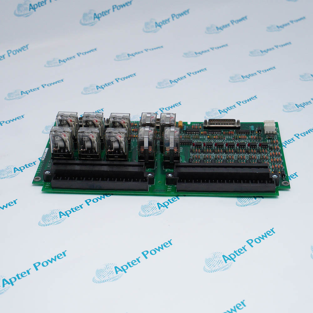
General Electric IS210MVRCH1A is a Mark Ve MVRC printed wiring assembly that reconnects retained C-core signals to the retrofit control module through HSSL.
In Stock
Ships by Tuesday, September 29
Fast Shipping Available
Get a quick price for IS210MVRCH1A
Quantity
*E-mail
Company
*Mobile
*Content
Upload (gif, jpg, jpeg, png, bmp, doc, docx, xls, xlsx, ppt, pdf, csv)

Technical specifications for IS210MVRCH1A

  • Manufacturer:
    General Electric
  • Part Number:
    IS210MVRCH1A
  • Product Family:
    GE Mark VI Gas Turbine Control
  • Product Type:
    Mark Ve MVRC PWA Assembly
  • Stock:
    1
  • Core Position:
    C core, location 2
  • Serial Link:
    CHSLA-J3 yellow HSSL
  • Controller Endpoint:
    UCSA1-R/SL1
  • Standard Connections:
    2PL, JC, JAA, JBB, JCC, JDD, JAR, JAS, JAT and JPD
  • Optional Connections:
    JHH, JII and JMP
  • Power Route:
    JPDV power path
  • Tariff Code:
    8537101190
  • Country of origin:
    USA
  • Place of shipment:
    Xiamen,Fujian,China
By purchasing this item, you agree to the Terms & Conditions, ApterPower is not an authorized distributor for listed manufacturers or tradenames and therefore the manufacturer's warranty does not apply. All our products come with ApterPower's 1-year warranty.

More Information

Overview Manuals Core Wiring HSSL Route Connector Map Retrofit Layout

Features:

  • Occupies location 2 in the retrofit C core.
  • Combines retained signal connections with a yellow HSSL path.
  • Supports optional JHH, JII and JMP circuits when fitted.
IS210MVRCH1A provides the MVRC connection point for the C-core portion of a Mark V-to-Mark Ve steam-control retrofit.

Retained harnesses terminate on the assembly while the serial path continues to the updated control module.

The cable check separates standard and optional connections before the core frame is closed.

The General Electric IS210MVRCH1A Mark Ve MVRC PWA Assembly is listed as Active / Available from OEM. Apter Power can support identification and configuration review.
General Electric IS210MVRCH1A Mark Ve MVRC PWA Assembly Manuals,Datasheets,Link Important Notice: Other accessories, manuals, cables, calibration data, software, etc. are not included with this equipment unless listed in the above stock item description. All prices are shown in USD.

Retained Harnesses

  • Core location: IS210MVRCH1A is fitted at C-core location 2.
  • Main cable set: 2PL, JC, JAA, JBB, JCC, JDD, JAR, JAS, JAT and JPD remain accounted for.
  • Optional paths: JHH, JII and JMP are connected only when the original arrangement includes them.
  • Routing check: Each cable is verified before the hinged frame is returned to its closed position.

Serial-Link Path

  • Board endpoint: The yellow HSSL cable terminates at CHSLA-J3.
  • Controller endpoint: The opposite end reaches UCSA1-R/SL1.
  • Cable identity: The C-core link uses the documented yellow cable assignment.
  • Physical route: The HSSL cable passes beneath the board frames toward the control module.

Connection Groups

  • Logic feed: 2PL is part of the required IS210MVRCH1A connection set.
  • Field groups: JAA through JDD and JAR through JAT retain their designated C-core paths.
  • Power interface: JPD participates in the control-module power route.
  • Expansion allowance: Optional JHH, JII and JMP positions remain dependent on the installed hardware.

Frame Arrangement

  • Mounting point: IS210MVRCH1A replaces the former location-2 board arrangement in the C core.
  • Access sequence: The hinged frame is lowered for cable attachment and verification.
  • Door clearance: Ethernet and HSSL routing is dressed away from the enclosure door.
  • Final condition: The frame is latched only after cable presence and endpoints are checked.
Description
General Electric IS210MVRCH1A is the MVRC printed wiring assembly installed in the C core of a Mark V-to-Mark Ve steam-control retrofit. The assembly occupies location 2 and carries the retained C-core connections into the updated control arrangement.

The cable field on IS210MVRCH1A receives 2PL, JC, JAA, JBB, JCC, JDD, JAR, JAS, JAT and JPD, with JHH, JII and JMP used only when those optional circuits are present. This connector grouping preserves the existing C-core paths while moving them onto the MVRC assembly.

A yellow high-speed serial link connects IS210MVRCH1A at CHSLA-J3 to the UCSA1-R/SL1 connection on the C control module. Power routing is completed through the JPDV path, so the HSSL, power and retained ribbon-cable routes remain separate parts of the retrofit wiring.

Before the C-core frame is closed, IS210MVRCH1A requires verification of every fitted connector against the site arrangement. Optional cables remain configuration-dependent, and the documented routing keeps the HSSL cable and retained harnesses clear of the enclosure door.
Alternative Names
GE IS210MVRCH1A IS210-MVRC-H1A General Electric MVRC H1A IS210 MVRC H1A IS210MVRCH1-A Mark Ve MVRC Assembly H1A MVRC C-Core Board H1A IS210MVRCHIA
Technical notes
General Electric IS210MVRCH1A is an MVRC C-core printed wiring assembly for Mark V-to-Mark Ve retrofit hardware.
Exceptional Service

Our Mission

  • 100% Satisfaction

    We believe expertise is priceless. With over 20 years of experience, and top engineers on staff, we can help you solve or avoid problems that threaten your business.
  • Trust Guaranteed

    Not only do we have a vast inventory, our team makes sure every piece of equipment is in working condition. Your purchases are also backed by our Warranty.
  • Expertise

    Time is money, especially when your equipment is down. We work quickly to get your equipment on its way so you can get it back up and running.

FAQS

The following is a list of questions commonly asked by our customers. Please contact us if you have a question about our process that is not answered below.
Which retained cables must be identified before IS210MVRCH1A is removed?
Before removing IS210MVRCH1A, record 2PL, JC, JAA, JBB, JCC, JDD, JAR, JAS, JAT and JPD, plus any fitted JHH, JII or JMP leads.
Why can an IS210MVRCH1A installation lose communication even when the board is seated?
IS210MVRCH1A depends on the yellow HSSL path from CHSLA-J3 to UCSA1-R/SL1, so both endpoints and the routed cable must be checked.
How does a site team confirm that IS210MVRCH1A is in the correct position?
IS210MVRCH1A belongs at location 2 in the C core; the frame position and documented connector set should agree before wiring is restored.
What should be done with unused optional leads around IS210MVRCH1A?
For IS210MVRCH1A, JHH, JII and JMP are connected only when the original C-core arrangement includes those optional circuits; unused leads should not be invented or reassigned.
Where should diagnosis begin when IS210MVRCH1A has an HSSL connection but remains inactive?
A connected HSSL cable does not prove that IS210MVRCH1A is powered; verify the JPD/JPDV power route separately from the CHSLA-J3 serial path.
Why should the HSSL cable route be inspected separately from the retained harnesses on IS210MVRCH1A?
IS210MVRCH1A uses HSSL for the control-module serial link while the other connectors preserve existing C-core circuits, so the two routes serve different paths.
What can prevent the enclosure door from closing cleanly after IS210MVRCH1A work?
Poorly dressed HSSL or Ethernet routing can interfere with door clearance; IS210MVRCH1A cabling should remain beneath the frames and away from the door surface.