Ask our team:
  • Phone: +86 181 0690 9650
  • E-Mail info@apterpower.com
  • Lifecycle status

    Active / Available from OEM
    Apter Power supplies DS200QTBAG1A for compatible Mark V RST signal layouts.

DS200QTBAG1A

/ 4.9
1001 reviews | Need a Specific Revision?
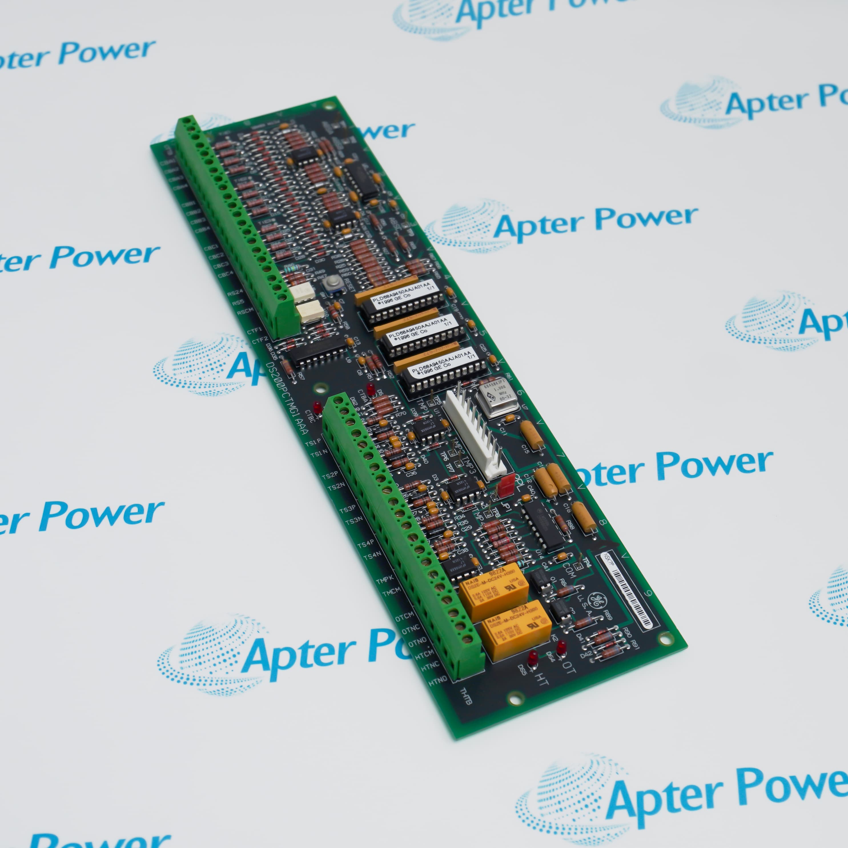
General Electric DS200QTBAG1A is a Mark V RST termination board that lands field signals for the R, S, and T control cores.
In Stock
Ships by Tuesday, September 29
Fast Shipping Available
Get a quick price for DS200QTBAG1A
Quantity
*E-mail
Company
*Mobile
*Content
Upload (gif, jpg, jpeg, png, bmp, doc, docx, xls, xlsx, ppt, pdf, csv)

Technical specifications for DS200QTBAG1A

  • Manufacturer:
    General Electric
  • Part Number:
    DS200QTBAG1A
  • Product Family:
    SPEEDTRONIC Mark V
  • Product Type:
    Mark V RST Termination Board
  • Stock:
    1
  • Board Function:
    RST field termination
  • Control Platform:
    SPEEDTRONIC Mark V
  • Terminal Blocks:
    TB1 and TB2
  • Terminations:
    72 positions per block
  • Primary Connector:
    JFF, 40-pin
  • Secondary Connector:
    JGG, 34-pin
  • Tariff Code:
    8537101190
  • Country of origin:
    USA
  • Place of shipment:
    Xiamen,Fujian,China
By purchasing this item, you agree to the Terms & Conditions, ApterPower is not an authorized distributor for listed manufacturers or tradenames and therefore the manufacturer's warranty does not apply. All our products come with ApterPower's 1-year warranty.

More Information

Overview Manuals Field Termination Servo & LVDT Signal Routing Core Connections

Features:

  • Provides 144 identified field-wire positions across two 72-point terminal blocks.
  • Routes servo, LVDT, magnetic-pickup, and transducer signals for the RST cores.
  • Connects board-level paths through dedicated 40-pin JFF and 34-pin JGG interfaces.
DS200QTBAG1A centralizes varied field signals at a common Mark V termination point before they reach control boards.

TB1 and TB2 numbering keeps each sensor, excitation, or output conductor tied to a defined channel position.

Separate connector groups carry the terminated paths onward to the associated core and signal-processing hardware.

The General Electric DS200QTBAG1A Mark V RST Termination Board may still be available for purchase and support from Apter Power beyond End-Of-Life (EOL) by the manufacturer (OEM).
General Electric DS200QTBAG1A Mark V RST Termination Board Manuals,Datasheets,Link Important Notice: Other accessories, manuals, cables, calibration data, software, etc. are not included with this equipment unless listed in the above stock item description. All prices are shown in USD.

TB1 and TB2 Wiring

  • Block Capacity: Each terminal block accommodates 72 separately identified signal wires.
  • Combined Count: The two blocks provide 144 field-termination positions in total.
  • Wire Identity: Connections are referenced by terminal-block name and terminal number.
  • Signal Mix: The blocks accept both measurement inputs and control-output wiring.

Position-Control Circuits

  • Servo Paths: Servo-valve output wiring terminates through the QTBA signal structure.
  • Excitation Paths: LVDT excitation outputs are distributed from dedicated termination points.
  • Feedback Route: Position-feedback signals continue from QTBA toward the related control circuitry.
  • Ground Limit: LVDT excitation outputs must not be shorted to ground.

Field Measurement Paths

  • Speed Pickups: High- and low-pressure magnetic pickup signals enter through the termination board.
  • Flow Pickups: Magnetic flow-driver and water-injection flow signals use defined QTBA points.
  • Power Inputs: Watt and VAR transducer paths are included among the landed signals.
  • Channel Mapping: Terminal labels preserve the connection between field wiring and control channels.

RST Interface Structure

  • Core Placement: QTBA boards support the corresponding R, S, and T core signal paths.
  • JFF Interface: The 40-pin JFF connector carries designated servo and LVDT-related circuits.
  • JGG Interface: The 34-pin JGG connector transfers a separate group of control signals.
  • Network Paths: IONET and COREBUS connections participate in the Mark V cabinet interface.
Description
Serving the R, S, and T control cores, General Electric DS200QTBAG1A is the Mark V QTBA termination board that concentrates field wiring before signals pass to the associated control circuitry.

Two terminal blocks on General Electric DS200QTBAG1A each provide positions for 72 signal wires, creating 144 individually identified field-termination points across TB1 and TB2.

Dedicated board interfaces on General Electric DS200QTBAG1A include the 40-pin JFF connector and the 34-pin JGG connector, alongside communication paths used by the Mark V core hardware.

Signal landing on General Electric DS200QTBAG1A covers magnetic speed and flow pickups, servo-valve outputs, LVDT excitation, water-injection flow measurement, and watt/VAR transducer input paths.
Alternative Names
General Electric DS200QTBAG1A GE DS200QTBAG1A DS200-QTBA-G1A DS200 QTBA G1A GE QTBA RST Termination Board General Electric Mark V QTBA Module DS200QTBAG1-A DS200QTBAGIA
Technical notes
General Electric DS200QTBAG1A is the Mark V RST termination interface for field pickups, servo and LVDT circuits, and core signal routing.
Exceptional Service

Our Mission

  • 100% Satisfaction

    We believe expertise is priceless. With over 20 years of experience, and top engineers on staff, we can help you solve or avoid problems that threaten your business.
  • Trust Guaranteed

    Not only do we have a vast inventory, our team makes sure every piece of equipment is in working condition. Your purchases are also backed by our Warranty.
  • Expertise

    Time is money, especially when your equipment is down. We work quickly to get your equipment on its way so you can get it back up and running.

FAQS

The following is a list of questions commonly asked by our customers. Please contact us if you have a question about our process that is not answered below.
What is terminated on DS200QTBAG1A?
General Electric DS200QTBAG1A lands Mark V field signals including magnetic pickups, servo outputs, LVDT excitation, and transducer inputs.
How many field wires can the terminal blocks on DS200QTBAG1A accept?
TB1 and TB2 on General Electric DS200QTBAG1A provide 72 positions each, for 144 identified terminations.
Which large connectors are fitted to DS200QTBAG1A?
General Electric DS200QTBAG1A includes the 40-pin JFF interface and the 34-pin JGG interface.
Where does DS200QTBAG1A operate in a Mark V cabinet?
The General Electric DS200QTBAG1A termination function is associated with the R, S, and T control-core signal paths.
Are LVDT excitation outputs routed through DS200QTBAG1A?
Yes. General Electric DS200QTBAG1A provides termination points for LVDT excitation and related position-feedback circuits.
Why must wire identifiers be preserved for DS200QTBAG1A?
Each General Electric DS200QTBAG1A connection is tied to a TB1 or TB2 terminal number, so the identifier preserves the intended signal route.